
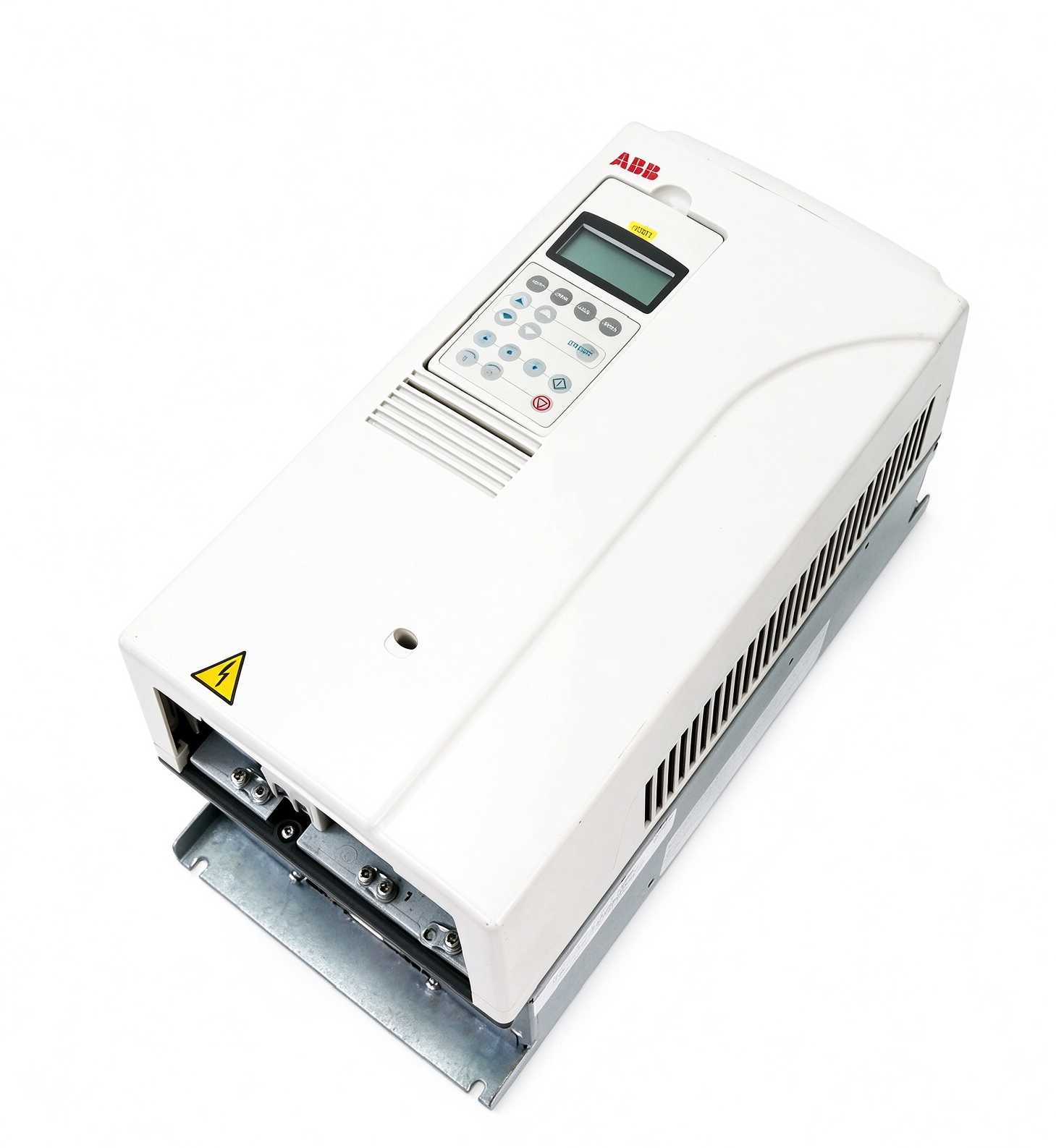
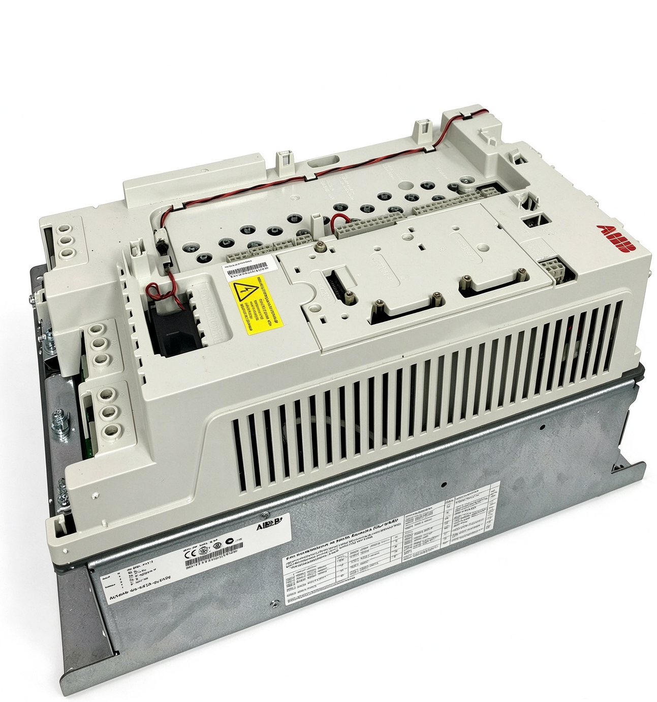
ABB ACS800-04-0035-3 D150 E200 J414 P901 P904 Industrial Variable Frequency Drive Module
The ABB ACS800-04-0035-3 is an industrial variable frequency drive module designed to regulate the speed and operation of compatible AC motors. The complete configuration includes D150, E200, J414, P901, and P904 option codes, which identify selected drive features and installation-related provisions. These details are important when reviewing equipment specifications, planning a replacement, or integrating the drive into an existing automation system. Before installation, the drive rating, supply requirements, motor characteristics, and option configuration should be checked against the applicable ABB technical documentation.
Product Overview
The ACS800-04 product family provides adjustable-speed control for industrial motor applications. A variable frequency drive converts incoming electrical power into a controlled output suitable for operating an AC motor at different speeds. By adjusting output frequency and managing motor voltage through its control system, the drive can support process requirements that vary with production conditions, mechanical loads, and operating cycles.
The ACS800-04-0035-3 designation identifies a specific drive module configuration. The complete model reference should be retained in maintenance records and procurement documentation because the option codes can distinguish units with different accessories or features. Two modules from the same drive family should not automatically be treated as identical merely because their base model numbers are similar.
This configuration includes a brake chopper option, an EMC/RFI filter option, a control panel holder, coated circuit boards, and an extended warranty designation. The specific implementation of each feature must be understood in the context of the original order and the installed equipment. The drive should be selected and operated according to its verified electrical ratings and application requirements.
Variable Frequency Drive Operating Principle
A variable frequency drive controls motor operation by regulating the electrical frequency delivered to the motor. For an AC motor, synchronous speed is related to supply frequency and the number of motor poles. In an induction motor, the actual shaft speed also depends on slip and the mechanical load. Adjusting the drive output frequency therefore allows the operating speed to be adapted to the requirements of the connected machine.
The drive’s power conversion stage uses controlled semiconductor switching to generate an appropriate motor supply. Its control system manages operating commands, current, voltage, and other relevant variables according to the installed control program. Correct motor data and parameter settings are important for stable operation and appropriate response to changing load conditions.
Drive selection must consider rated motor current, supply voltage, operating frequency, load characteristics, starting requirements, and duty cycle. The complete nameplate and the applicable ABB technical data should be consulted before determining whether this particular configuration is suitable for an installation. The model designation alone does not establish every permissible operating condition.
D150 Brake Chopper Function
The D150 option identifies a brake chopper in the ACS800-04 configuration documentation. A brake chopper is associated with the management of braking energy in compatible drive systems. During deceleration or other operating conditions that return energy from the motor to the drive, energy may accumulate in the DC link. Where a compatible braking resistor arrangement is provided, the brake chopper can control the transfer of energy to the resistor to help manage the DC-link voltage.
The brake chopper and braking resistor perform different functions. The chopper is the controlled switching element, while the resistor converts electrical energy into heat. The complete braking arrangement must be selected according to the drive configuration, braking duty, resistor specifications, and applicable installation instructions.
Not every application requires the same braking capability. The required performance depends on load inertia, deceleration time, frequency of braking events, and the mechanical system. The D150 designation should therefore be considered alongside the relevant technical documentation rather than treated as confirmation of a particular braking power or duty rating.
When a braking resistor is part of the installation, its mounting, ventilation, thermal protection, electrical connections, and permitted operating limits must be checked. Braking components can become hot during operation, so the installation must follow the prescribed safety clearances and protection requirements.
E200 EMC/RFI Filter
The E200 option identifies an EMC/RFI filter intended for a specified second-environment, grounded TN supply arrangement and drive category C3 in the referenced ACS800 documentation. Electromagnetic compatibility is important in industrial installations because switching power electronics can generate high-frequency disturbances that may affect nearby equipment if the installation is not designed appropriately.
An EMC filter helps manage conducted electromagnetic disturbances within the limits and conditions for which it is designed. However, the filter is only one part of an effective EMC installation. Cable selection, cable routing, grounding, bonding, cabinet layout, and the installation of motor cables can also influence overall electromagnetic performance.
The filter configuration must be suitable for the electrical supply and grounding arrangement. It should not be assumed that the E200 option is appropriate for every TN, IT, or other supply system. Engineers should verify the permitted supply configuration and any applicable installation restrictions before connecting the drive.
J414 Control Panel Holder
The J414 option identifies a control panel holder for specified ACS800 frame sizes. It is a mounting accessory intended to support the control panel arrangement rather than a designation that independently confirms the presence of a complete operator panel. The exact supplied configuration should be verified against the drive order documentation.
A suitable control panel arrangement allows authorized personnel to access supported drive functions, view operating information, and work with parameters according to the installed control program. The panel interface and its connection arrangement must be compatible with the drive and any applicable mounting accessories.
During installation, the holder should be fitted according to the manufacturer’s instructions and positioned so that the operator can access the interface without obstructing ventilation or maintenance access. The complete control arrangement should be checked before commissioning.
P901 Coated Circuit Boards and P904 Option
The P901 designation identifies coated circuit boards in the referenced ACS800-04 ordering information. Board coating provides an additional protective feature for the electronic assemblies under the conditions defined by the product design. It should not be interpreted as unrestricted protection against moisture, direct water exposure, corrosive chemicals, or every harsh industrial environment.
Environmental suitability must be evaluated using the drive’s permitted operating conditions and the requirements of the installation. Dust, temperature, humidity, vibration, and chemical exposure can influence equipment reliability. The drive should be installed in an environment that meets the applicable technical specifications.
The P904 designation identifies an extended warranty option in the referenced configuration documentation. It is a commercial or service-related designation rather than an additional motor-control function. The actual warranty coverage and applicable terms depend on the original order and relevant documentation.
Industrial Applications and Integration
Industrial variable frequency drives are used in many motor-driven applications, including pumps, fans, conveyors, compressors, and process machinery. Depending on its verified ratings and operating configuration, an ACS800-04 module may be integrated into a suitable industrial motor control system.
In pumping and fan applications, adjustable-speed operation can help match the motor to changing process demand. Conveyor systems may require controlled acceleration and deceleration, while other machinery may place greater emphasis on torque response or braking behavior. Application requirements should be evaluated before selecting the drive and any associated braking equipment.
Integration requires coordination between the drive, motor, protective devices, external control signals, and mechanical load. Control wiring and parameter settings must reflect the intended operating sequence. Where braking is required, the braking resistor and associated thermal provisions must also be included in the system design.
Installation, Commissioning, and Maintenance
Before installation, qualified personnel should verify the incoming supply, grounding arrangement, motor ratings, protective devices, cable specifications, and required cooling clearances. The drive module must be installed in a suitable cabinet or mounting arrangement according to the ACS800-04 hardware instructions. Power wiring, control wiring, and grounding connections should be completed in accordance with the manufacturer’s requirements and applicable electrical standards.
Commissioning should include verification of the motor nameplate data, drive parameters, control signals, and installed options. Where braking equipment is used, its compatibility and wiring should be checked before functional operation. Initial operation should follow the specified procedure, and unexpected faults or abnormal behavior should be investigated before the system is placed into normal service.
Routine maintenance may include reviewing fault history, inspecting cooling airflow, checking electrical connections, and examining the equipment for signs of overheating or contamination. The drive must be isolated according to the required safety procedures, and the specified DC-link discharge time must be observed before internal work begins. Maintenance should be carried out only by appropriately qualified personnel.
Replacement Selection and Conclusion
When selecting a replacement for the ABB ACS800-04-0035-3 D150 E200 J414 P901 P904, verify the full model reference and all associated option codes. Particular attention should be given to supply compatibility, drive ratings, braking requirements, EMC filter suitability, control panel mounting, and environmental conditions.
The ABB ACS800-04-0035-3 provides adjustable-speed motor control within an industrial drive system. Its specified options identify additional features that may affect installation and application suitability. Confirming the complete configuration against the relevant ABB documentation helps ensure that the selected module is appropriate for the intended system and supports reliable integration, operation, and maintenance.

评价
目前还没有评价