
ABB 2TLA030054R0000 INCA 1 Tina Emergency Stop Button
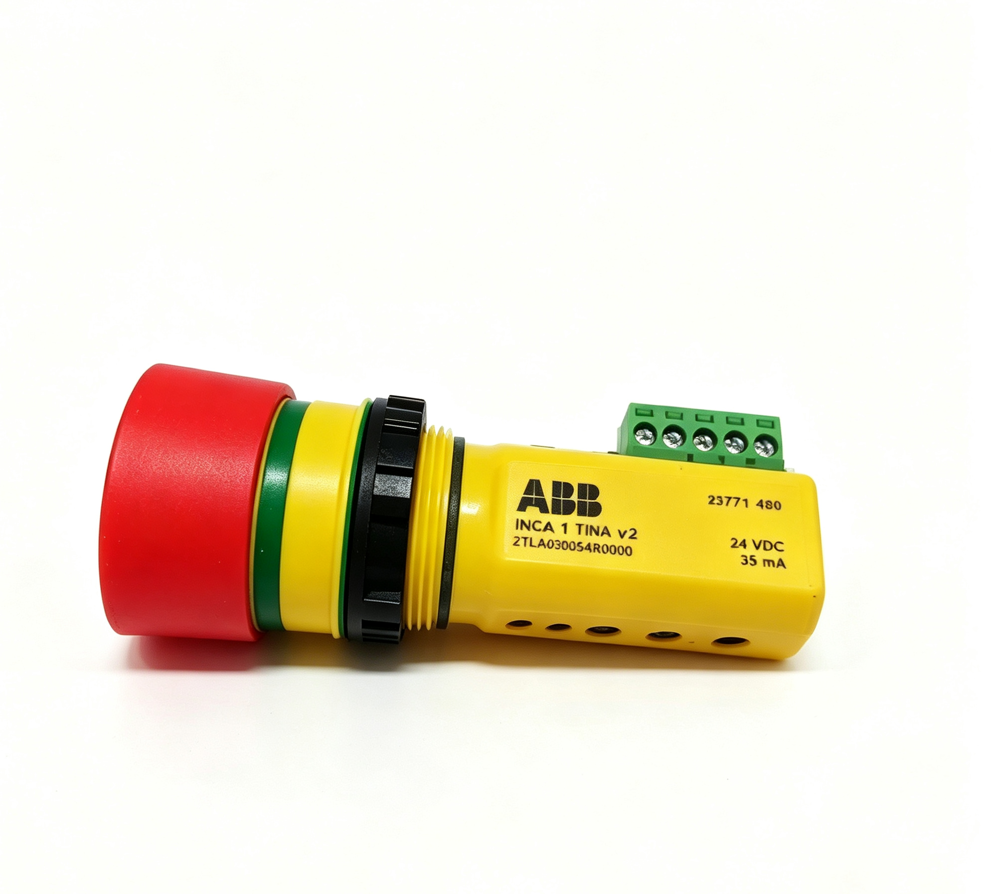
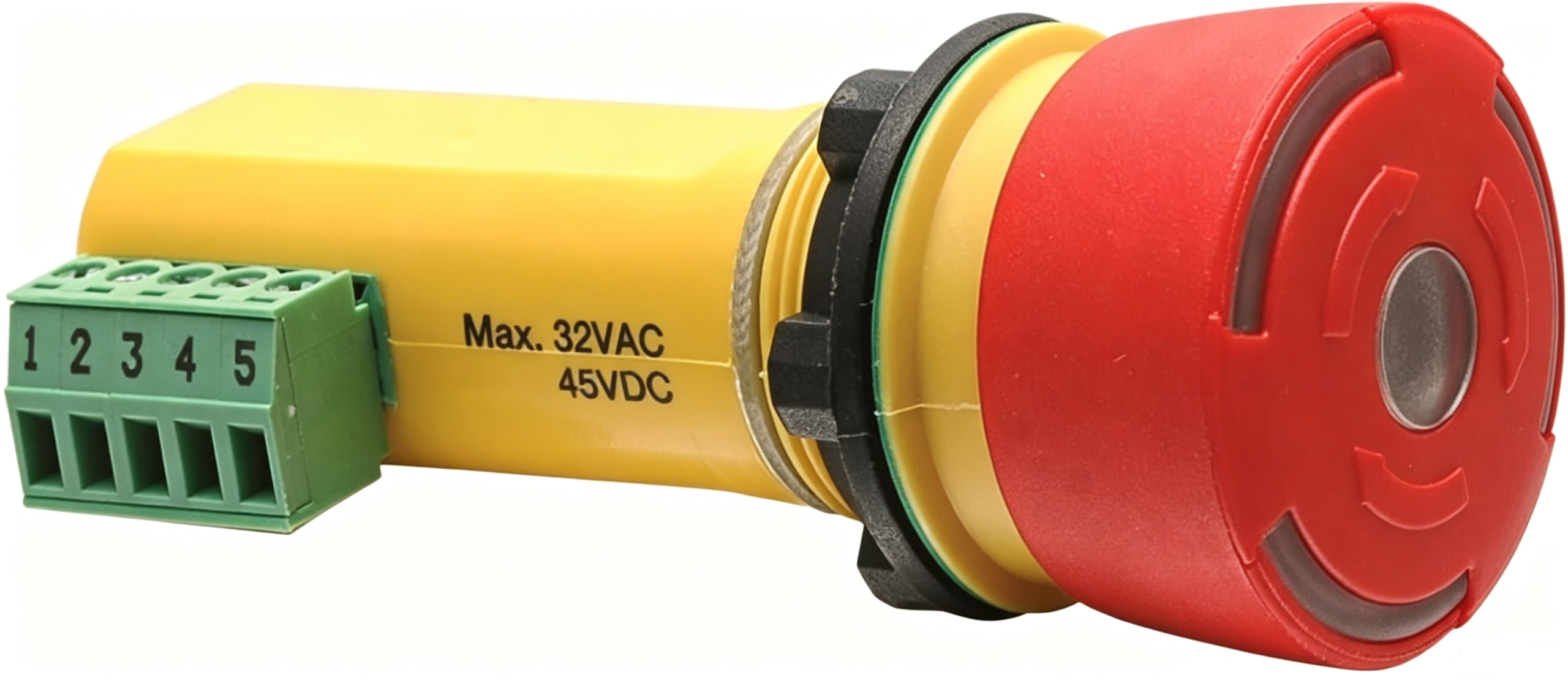
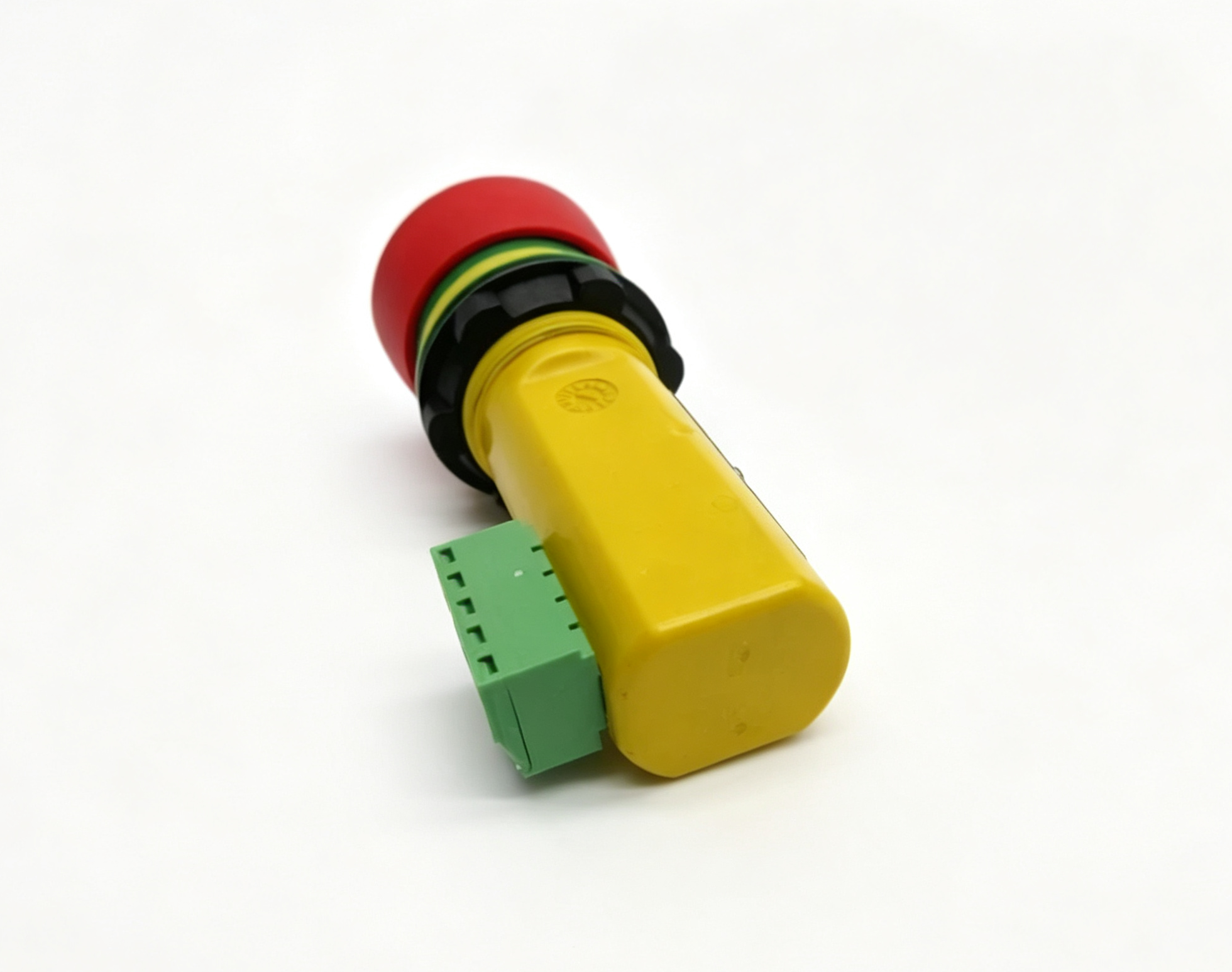
ABB 2TLA030054R0000 is the INCA 1 Tina emergency stop button designed for panel mounting in industrial safety applications. The device belongs to the ABB Jokab Safety range and combines an emergency stop actuator with a Tina adaptation unit, status indication and terminal connections. It is intended for integration into compatible dynamic safety circuits where the emergency stop condition must be detected and communicated as part of the machine safety architecture.
The complete product designation is important because the INCA family contains several variants with different functions and connection arrangements. ABB identifies 2TLA030054R0000 specifically as INCA 1 Tina. Its configuration includes a red emergency stop button, a 5-pin terminal block and Tina functionality for dynamic safety circuits. The device is designed around a 22.5 mm panel mounting opening, making it suitable for installation directly into control panels and machine operator interfaces.
Product Identification
- Manufacturer: ABB
- Product family: INCA
- Type: INCA 1 Tina
- Article number: 2TLA030054R0000
- Product category: Emergency stop button
- Mounting method: Panel mounting
- Mounting hole: 22.5 mm
- Safety technology: Tina / DYNlink
- Button color: Red
- Status indication: Integrated LED
- Connection: Terminal block
- LED operating voltage: 24 VDC
- Button protection: IP65
- Connector protection: IP20
- Mechanical life: More than 50,000 operations
INCA 1 Tina Emergency Stop Function
The primary function of ABB 2TLA030054R0000 is emergency stop operation within a machine safety system. An emergency stop device provides a clearly identifiable means for an operator to initiate a safety-related stop when a hazardous situation requires immediate intervention.
The INCA 1 Tina combines the physical emergency stop button with electronics intended for dynamic safety circuits. This configuration allows the device to participate in a safety architecture rather than functioning only as a conventional mechanical pushbutton.
When the button is actuated, the corresponding safety circuit condition changes and the compatible safety system can respond according to its configured logic. The actual machine response depends on the complete safety circuit, safety controller, monitored devices and machine control architecture.
Tina Adaptation and DYNlink Technology
A key characteristic of 2TLA030054R0000 is the Tina adaptation unit incorporated into the INCA 1 Tina design. ABB documentation identifies this version for dynamic safety circuits and DYNlink technology.
DYNlink is used within ABB safety systems to combine safety information and diagnostic information through compatible safety devices and controllers. The Tina interface allows an emergency stop device such as INCA 1 Tina to be integrated into an appropriate dynamic safety circuit.
This differs from a basic emergency stop button that provides only conventional contact outputs. The Tina version is intended for use within a compatible ABB safety architecture where the safety signal and device status are handled by the associated safety equipment.
Panel Mounting
The INCA 1 Tina uses a 22.5 mm mounting hole for panel installation. This dimension is commonly used for industrial control components and allows the emergency stop device to be incorporated into machine control panels, operator stations and electrical enclosures.
The mounting arrangement should provide sufficient mechanical support around the actuator and allow the button to be operated without obstruction. The panel thickness, mounting hardware and clearance should be checked against the applicable mechanical drawing before installation.
Correct mounting is important because the emergency stop actuator must remain accessible and mechanically reliable during repeated operation.
Status LED Indication
ABB 2TLA030054R0000 includes a status LED integrated into the emergency stop button. The LED provides visual information associated with the condition of the safety device and safety circuit.
ABB documentation specifies a 24 VDC operating voltage for the INCA 1 Tina LED and approximately 47 mA current consumption for the LED circuit. The indication behavior depends on the safety system configuration and the condition of the connected safety circuit.
A visible status indication can assist operators and maintenance personnel in identifying the general condition of the safety device without requiring access to the internal wiring.
Safety Circuit Integration
The INCA 1 Tina should be considered as one component within a complete machine safety system. The emergency stop device may be connected to compatible ABB safety controllers, safety relays or other DYNlink components depending on the architecture.
The emergency stop signal must be processed by equipment appropriate for the required safety level of the machine. The final safety function is determined by the complete system design, including the emergency stop device, safety controller, actuators, monitored equipment and wiring.
For this reason, the article number alone does not define the safety level of an entire machine. System architecture and risk assessment remain essential parts of the safety design.
Protection Ratings
ABB technical documentation specifies an IP65 protection class for the INCA 1 Tina button and IP20 protection for the connector. These ratings apply to the respective parts of the device and should be considered when designing the surrounding enclosure and wiring system.
The IP65 button rating provides protection against dust ingress and water jets under the conditions defined by the applicable standard. The IP20 connector rating means that the connection area requires suitable environmental protection when installed in an enclosure or panel.
The actual protection of the complete installation depends on the panel, enclosure, cable entry system and installation method.
Electrical Characteristics
The integrated LED of the INCA 1 Tina operates from a nominal 24 VDC supply. ABB documentation specifies a permitted LED supply range of 24 VDC +15% and -25%.
The Tina version is intended for dynamic safety circuits rather than simple conventional contact switching. The terminal block provides the electrical interface required for connection within the compatible safety architecture.
Wiring should follow the applicable ABB connection diagram. The terminal assignment should not be inferred from another INCA variant because different versions may have different circuit arrangements.
Mechanical and Environmental Characteristics
The INCA 1 Tina is designed for industrial control-panel environments. ABB documentation lists a polyamide PA66, Macromelt and polybutylene terephthalate material construction for the relevant device components.
The specified operating temperature range is -10°C to +55°C, while the documented storage temperature range is -30°C to +70°C. These values should be considered together with the environmental conditions of the complete machine enclosure.
The documented mechanical life exceeds 50,000 operations, providing a defined reference for repeated actuator use within the intended application.
Technical Specification Table
| Parameter | ABB 2TLA030054R0000 |
|---|---|
| Product name | INCA 1 Tina Emergency Stop |
| Article number | 2TLA030054R0000 |
| Product family | INCA |
| Safety interface | Tina / DYNlink |
| Product type | Panel-mounted emergency stop button |
| Button | Red emergency stop actuator |
| Mounting hole | 22.5 mm |
| Connection | 5-pin terminal block |
| LED operating voltage | 24 VDC +15% / -25% |
| LED current consumption | Approximately 47 mA |
| Button protection | IP65 |
| Connector protection | IP20 |
| Operating temperature | -10°C to +55°C |
| Storage temperature | -30°C to +70°C |
| Mechanical life | More than 50,000 operations |
| Weight | Approximately 45 g |
Emergency Stop Indicator Behavior
The integrated LED provides a visual indication of the condition of the INCA 1 Tina and its associated safety circuit. ABB documentation describes green indication for a functioning safety device and safety circuit, while flashing indication can identify a condition in which the safety device is functioning but the safety circuit has previously been interrupted. A red indication corresponds to the emergency stop button being pressed and the safety circuit being interrupted.
The indicator should be interpreted together with the complete safety system rather than used as the only diagnostic method. A machine safety fault can originate from another device or section of the connected circuit.
Safety Performance
ABB documentation specifies that the INCA 1 Tina can achieve up to Performance Level e, Category 4 according to EN ISO 13849-1, depending on the complete system architecture. It also lists SIL 3 capability according to the relevant safety standards when the required system conditions are fulfilled.
These classifications describe the possible performance of the safety device within an appropriately designed safety system. They should not be interpreted as an automatic safety rating for every machine installation.
The final safety performance must be determined through the complete machine risk assessment, architecture, diagnostics and validation process.
Application in Industrial Machinery
ABB 2TLA030054R0000 can be integrated into machine operator panels where an emergency stop function is required. The 22.5 mm panel mounting arrangement makes it suitable for control cabinets, machine panels and dedicated operator interfaces.
Its Tina and DYNlink functionality allows the device to be incorporated into compatible ABB safety systems with other safety components. This can simplify the connection of safety devices within an appropriately designed architecture.
The exact application depends on the machine risk assessment and the safety control system selected by the equipment designer.
Maintenance and Inspection
Inspection of the INCA 1 Tina should include the actuator, mounting arrangement, terminal connections and surrounding panel components. The emergency stop button should remain mechanically accessible and should not be obstructed by other equipment.
The LED indication can provide useful information about the safety circuit condition, while the associated safety controller can provide additional diagnostic information. Any unexpected indication or safety interruption should be investigated through the complete safety circuit.
Terminal connections should be checked according to the applicable wiring documentation, and the safety function should be validated according to the machine’s established safety procedures.
Product Variant Identification
The INCA family contains several related products, including INCA 1, INCA 1 Tina, INCA 1S Tina and other variants. These products are not identical even when their external form appears similar.
ABB identifies 2TLA030054R0000 specifically as INCA 1 Tina. The related 2TLA030054R0100 is INCA 1, while 2TLA030054R0200 is INCA 1S Tina. The different article numbers correspond to different safety functions and electrical configurations.
For this reason, the complete article number should always be checked before selecting a corresponding component for a particular safety circuit.
Product Lifecycle Identification
ABB issued a product change notification identifying 2TLA030054R0000 as the earlier INCA 1 Tina model and 2TLA030054R0010 as the corresponding newer INCA 1 Tina V2 model. This information is relevant when documenting existing equipment and evaluating product substitutions.
A replacement should not be selected solely because the product name is similar. The electrical interface, dimensions, safety architecture and compatibility with the installed ABB safety system should be verified before making a substitution.
Conclusion
ABB 2TLA030054R0000 is the INCA 1 Tina emergency stop button designed for panel mounting in industrial safety applications. It uses a 22.5 mm mounting hole and incorporates a Tina adaptation unit for dynamic safety circuits, an integrated status LED and a 5-pin terminal block.
The device is associated with ABB DYNlink safety technology and is intended to operate as part of a compatible safety architecture. ABB technical documentation specifies a 24 VDC LED supply, approximately 47 mA LED consumption, IP65 protection for the button, IP20 protection for the connector and more than 50,000 mechanical operations.
For technical identification, the complete article number 2TLA030054R0000 and the type designation INCA 1 Tina should be retained together. Because related INCA products have different functions and connection configurations, accurate identification is particularly important when documenting or evaluating an existing machine safety system.
评价
目前还没有评价