
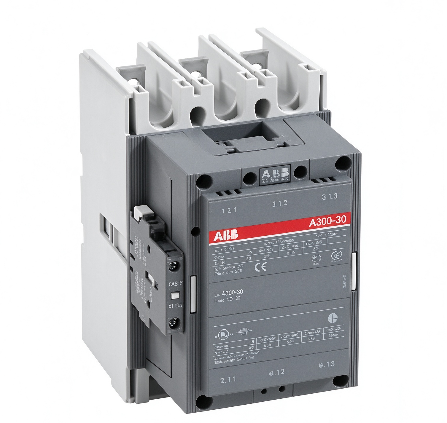
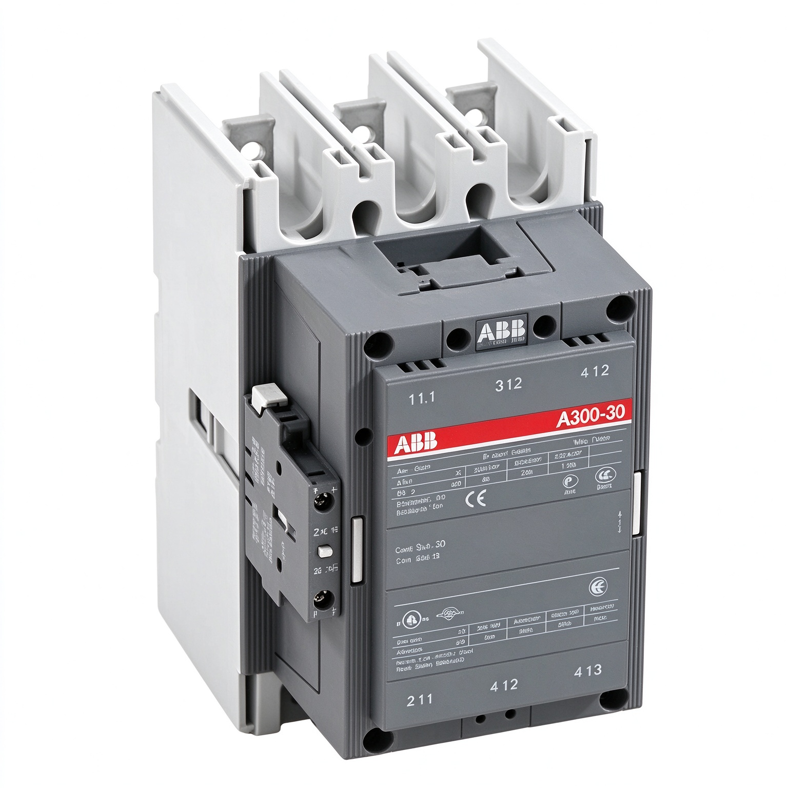
ABB 1SFL551001R8422 A300-30-22-84 Three-Pole Power Contactor
Product Overview
The ABB 1SFL551001R8422 is associated with the A300-30-22-84 power contactor, a three-pole switching device designed for industrial electrical systems. Contactors provide a controlled method of connecting and disconnecting power circuits. They are commonly incorporated into motor starters, distribution assemblies, isolation arrangements, and other electrical control panels where remote switching is required.
The A300 contactor family is intended for applications involving substantial electrical loads. The 1SFL551001R8422 ordering reference identifies a particular configuration within this product range. When selecting or replacing a contactor, the complete catalog number should be checked against the equipment documentation, nameplate, and electrical design. Similar-looking contactors may differ in coil voltage, auxiliary contact arrangement, or switching ratings.
A300-30-22-84 Model Identification
The model designation A300-30-22-84 provides a product-family and configuration reference. The A300 series is used in industrial power-control applications, while the associated catalog number identifies the specific contactor version. The 1SFL551001R8422 designation is therefore important for procurement, maintenance records, and replacement-part identification.
The suffix is particularly relevant when checking the control circuit. The A300-30-22-84 version is specified for a 110 V AC control supply at 50 Hz and a 110–120 V AC control supply at 60 Hz. These values refer to the contactor’s control circuit and should not be confused with the voltage switched by its main contacts.
Three-Pole Main Circuit
The contactor uses three main poles to switch a three-phase power circuit. When the operating coil is energized under the specified conditions, the main contacts change state and establish the intended electrical connection. When the coil is de-energized, the mechanism returns to its normal state, opening the main circuit.
This operating principle allows a control system to manage a higher-power load through a separate control circuit. A contactor is not, by itself, a complete motor-protection system. Depending on the installation, overload protection, short-circuit protection, isolation, and other protective functions must be provided by appropriately selected devices.
Control Coil and Operating Voltage
The control coil is a defining feature of the ABB 1SFL551001R8422 configuration. Its specified control voltage is 110 V AC at 50 Hz and 110–120 V AC at 60 Hz. The control supply must be compatible with the electrical circuit that commands the contactor. Applying an unsuitable voltage or frequency can prevent correct operation and may damage the coil.
Before installation, verify the control voltage available in the panel and confirm the frequency of the supply. The control-circuit wiring diagram should also be checked to establish the correct connection points. Where the contactor is operated by a PLC, relay, push-button station, or other control device, the interface circuit must be designed for the coil’s electrical requirements.
Electrical Switching Applications
The A300 contactor range can be used in industrial switching applications such as motor starting, power-circuit control, isolation arrangements, and bypass circuits. The suitability of a particular contactor depends on the load type, operating voltage, current, switching frequency, ambient conditions, and applicable utilization category.
For motor applications, the AC-3 rating is relevant because it addresses the switching duty associated with starting and switching off running squirrel-cage motors. The published A300-30 data includes an AC-3 operational current of 300 A at 415 V and 55°C. The applicable rating must always be checked for the actual operating voltage and installation conditions. Ratings at one voltage or temperature should not be assumed to apply unchanged to another operating point.
For less demanding switching duties, such as certain resistive or mixed loads, a different utilization category may apply. The appropriate selection should be made using the manufacturer’s technical tables and the load characteristics rather than relying only on a single current value.
Rated Operational Voltage and Current
The A300-30 contactor is designed for use in power circuits with rated operational voltages up to 690 V, subject to the applicable ratings and installation requirements. Its conventional free-air thermal current and operational current depend on the utilization category, voltage, ambient temperature, and other specified conditions.
For reference, the A300-30 family data lists a conventional free-air thermal current of 500 A and an AC-1 operational current of 500 A at 690 V and 40°C. The AC-1 rating is reduced at higher ambient temperatures in the published rating table. These values describe different operating conditions and should not be treated as interchangeable with the AC-3 motor-switching rating.
When engineering a contactor circuit, consider both the steady-state load and the electrical stresses associated with switching. The contactor’s short-circuit coordination requirements, protective-device selection, conductor sizing, and thermal conditions must be evaluated as part of the complete assembly.
Auxiliary Contacts and Control Logic
Auxiliary contacts are used in control circuits for functions such as electrical interlocking, status indication, holding circuits, and signaling. The A300-30-22 configuration indicates an auxiliary-contact arrangement distinct from versions with other contact configurations. The exact normally open and normally closed contact arrangement should be verified against the relevant ABB connection diagram before wiring.
Auxiliary contacts should be selected and applied according to their own electrical ratings. Their control-circuit function is different from that of the main power contacts, and the main-contact current rating must not be applied to auxiliary circuits.
Installation and Panel Integration
The contactor should be installed by qualified personnel in accordance with the equipment documentation and applicable electrical regulations. Before work begins, isolate the relevant power sources and follow the site’s lockout and verification procedures. Confirm that the mounting arrangement, clearances, conductor sizes, terminal connections, and enclosure conditions are suitable for the application.
Power conductors should be connected to the designated main terminals, while the coil and auxiliary circuits should be wired according to the contactor’s terminal markings. Tightening torques and conductor preparation requirements should be taken from the manufacturer’s instructions. Loose connections can cause excessive heating, voltage drop, and unreliable operation.
Allow sufficient space for heat dissipation and maintenance access. The contactor should be used within its specified environmental limits, and the panel design should account for ambient temperature, ventilation, contamination, and vibration where relevant.
Inspection and Maintenance
Routine inspection should follow the maintenance plan for the electrical installation. With the equipment safely isolated, qualified personnel can check the contactor’s mounting, terminal condition, wiring, and visible signs of overheating or mechanical damage. The operating mechanism should be inspected in accordance with the manufacturer’s procedures.
Abnormal noise, inconsistent switching, excessive contact wear, or evidence of overheating should be investigated before the equipment is returned to service. Maintenance intervals depend on the switching duty, operating environment, and equipment condition. Any replacement components must match the required electrical and mechanical configuration.
Replacement and Model Verification
When replacing an installed contactor, verify the complete part number rather than selecting a device based only on its external appearance or nominal current. Confirm the control-coil voltage and frequency, main-circuit ratings, number of poles, auxiliary-contact arrangement, mounting dimensions, terminal layout, and compatibility with associated accessories.
The ABB 1SFL551001R8422 reference should be compared with the existing nameplate and the original equipment documentation. If the contactor is part of a motor starter or control assembly, also review the overload relay, short-circuit protective device, wiring diagram, and control logic. These checks help establish whether the selected configuration is suitable for the intended circuit.
Technical Summary
ABB 1SFL551001R8422 corresponds to the A300-30-22-84 three-pole power contactor configuration. It is intended for industrial power switching and control applications, including suitable motor-control circuits. The specified coil supply is 110 V AC at 50 Hz and 110–120 V AC at 60 Hz. The A300-30 family provides ratings for different utilization categories and operating conditions, so the relevant technical table must be consulted for the actual application.
Accurate identification of the catalog number, control voltage, contact arrangement, and load requirements is essential when specifying or replacing this contactor. Using the complete model reference alongside the manufacturer’s documentation supports correct integration into industrial electrical panels and motor-control systems.

评价
目前还没有评价