
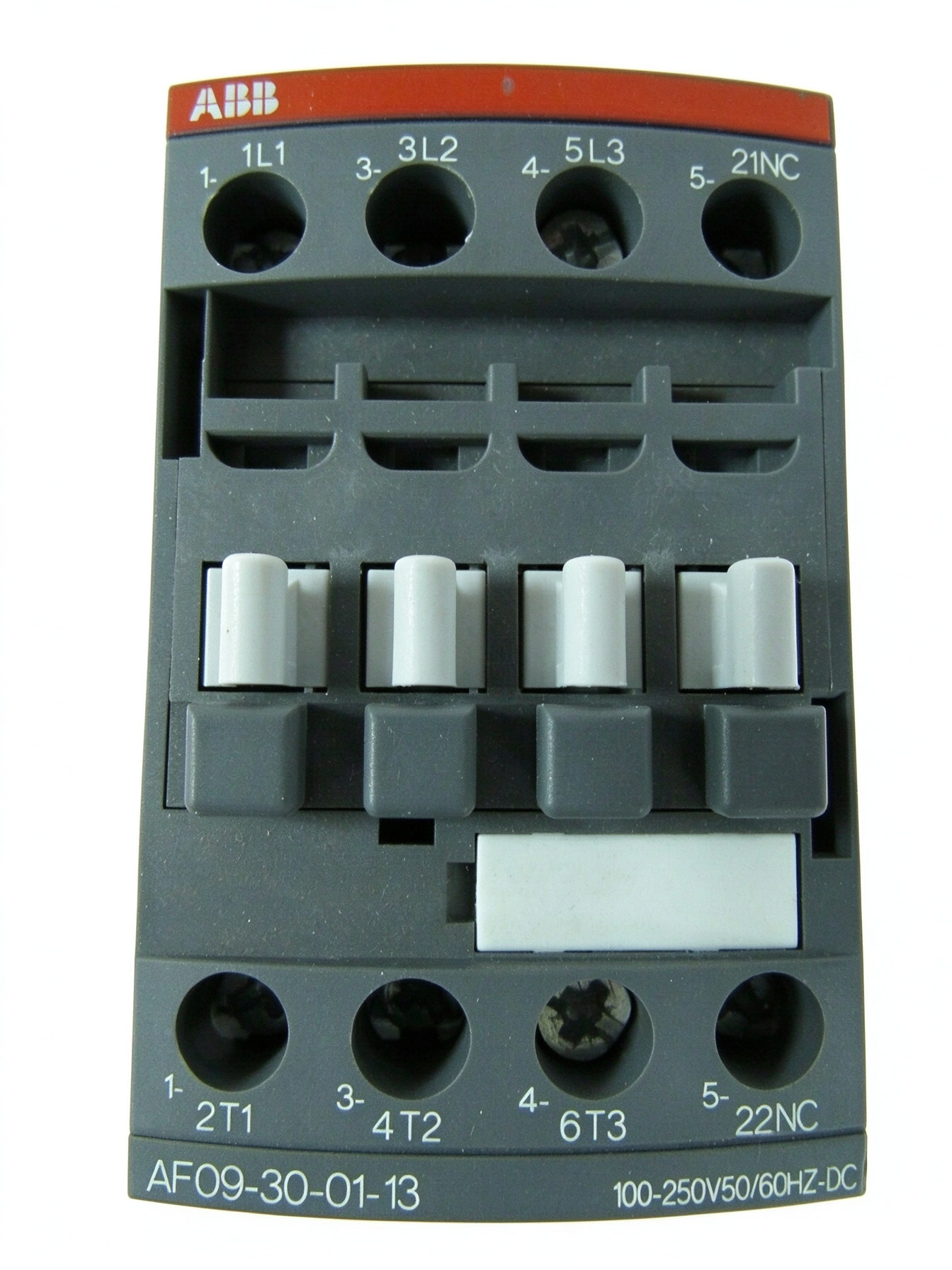
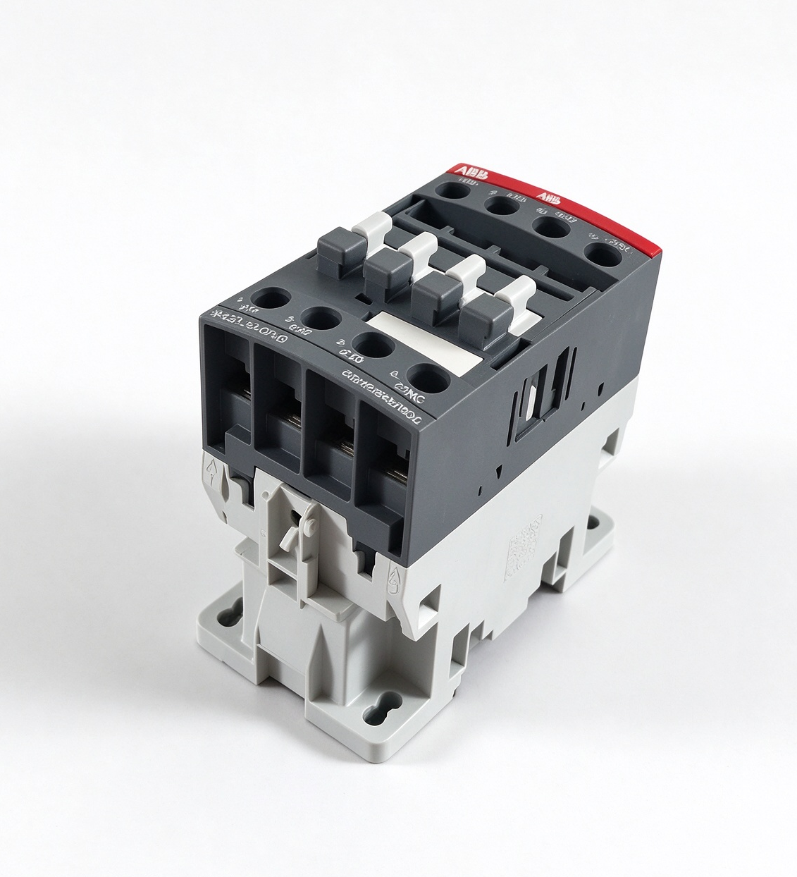
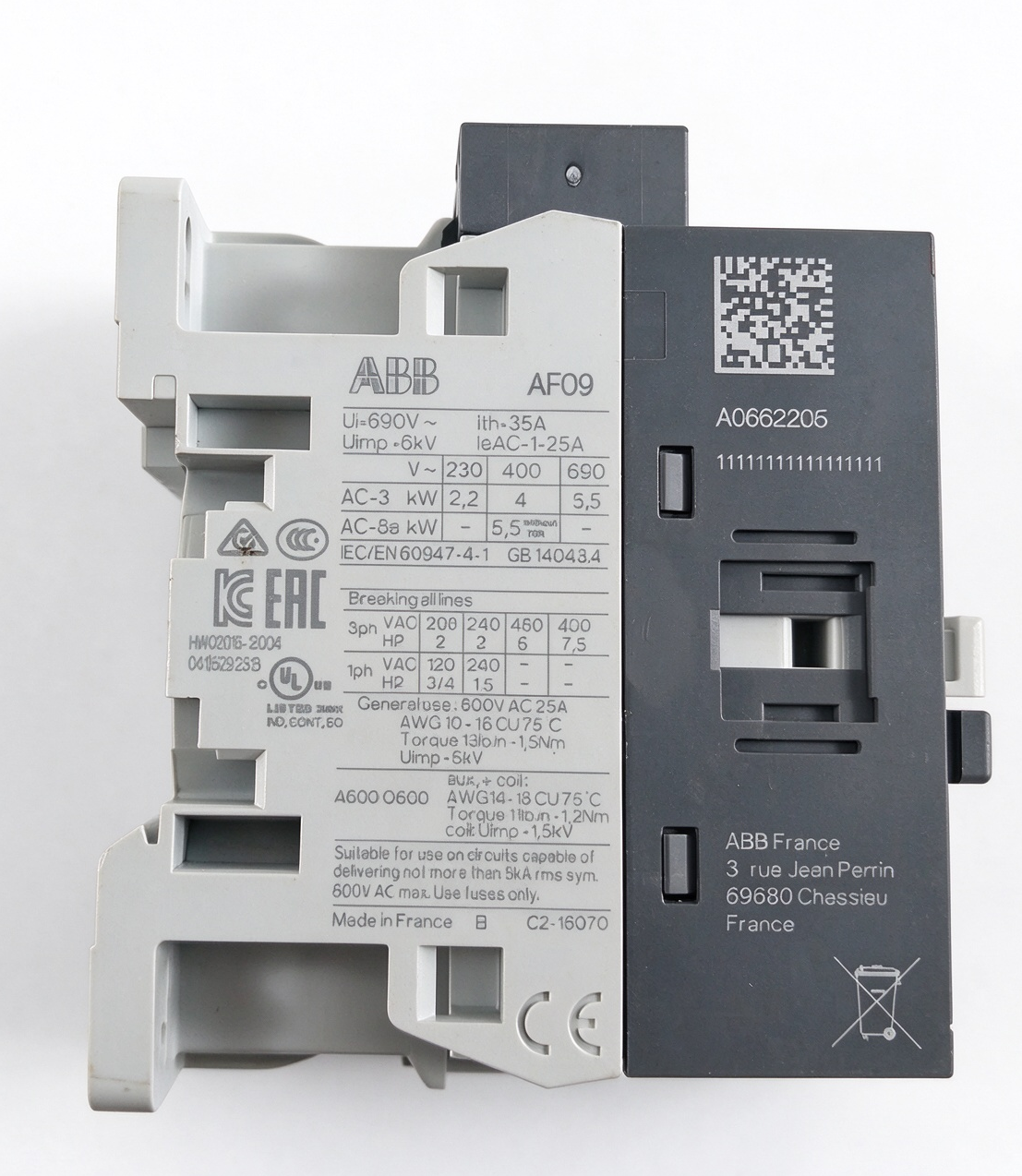
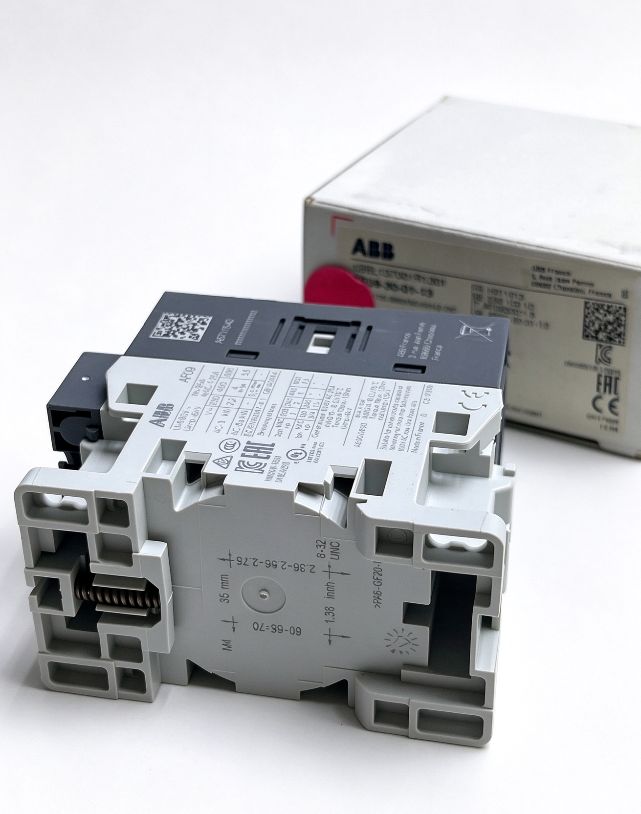
ABB 1SBL137001R1301 AF09-30-01-13 Contactor
The ABB 1SBL137001R1301 is an AF09-30-01-13 three-pole contactor designed for industrial motor switching and power circuit control. It belongs to the ABB AF contactor family and combines a wide-range electronic coil interface, integrated surge protection, and a built-in normally closed auxiliary contact. These features support its use in motor starters, electrical control panels, and automation equipment where dependable switching and coordination between control and power circuits are required.
Product Overview
The AF09-30-01-13 is intended to establish and interrupt electrical connections in accordance with the requirements of the connected load and control system. Its three main poles allow it to switch the three phases of a typical AC motor circuit. The contactor operates through an electromagnetic mechanism controlled by an electrical coil interface. When the control circuit energizes the coil within its specified range, the main contacts change state. When the control signal is removed, the mechanism returns to its de-energized position.
Product identification is important when selecting a replacement or specifying a component for a new panel. The ordering code 1SBL137001R1301 identifies this particular ABB contactor, while AF09-30-01-13 is its extended type designation. The suffix 13 is associated with the wide-range 100–250 V AC/DC coil version. The 01 contact arrangement identifies the built-in normally closed auxiliary-contact configuration, distinguishing it from related versions that use a normally open auxiliary contact.
Key Technical Characteristics
- Manufacturer: ABB
- Product type: AF series industrial contactor
- Model designation: AF09-30-01-13
- Order code: 1SBL137001R1301
- Main pole configuration: Three poles
- Built-in auxiliary contact: One normally closed contact
- Control voltage range: 100–250 V AC, 50/60 Hz, or DC within the specified range
- Rated operational voltage: Up to 690 V AC under applicable IEC ratings
- AC-3 motor rating: Up to 4 kW at 380–400 V
- AC-1 operational current: Up to 25 A under the specified rating conditions
- Connection method: Screw terminals
- Surge protection: Integrated into the contactor design
These ratings describe different operating conditions and should not be treated as interchangeable values. AC-1 applies to specified non-inductive or slightly inductive loads, whereas AC-3 is associated with squirrel-cage motor starting and switching during normal operation. The permitted current and power depend on the load category, supply voltage, ambient temperature, and applicable standards. The relevant ABB technical documentation should be consulted before final equipment selection.
Wide-Range AC/DC Coil Technology
A key characteristic of the ABB 1SBL137001R1301 is its electronic coil interface. Rather than relying on a narrow coil-voltage specification, this AF contactor accepts a control voltage across a range of 100–250 V AC at 50 or 60 Hz, or DC within the manufacturer’s specified limits. This arrangement can simplify panel design when the available control supply varies between installations or when equipment must accommodate different control-power standards.
The electronic interface is designed to manage substantial variations in control voltage while maintaining the contactor’s intended operating behavior. This is particularly relevant in industrial facilities where control circuits may experience voltage fluctuations associated with supply conditions or switching events. The specified voltage range must nevertheless be respected; a wide-range coil does not mean that any voltage can be applied.
Because AC and DC operation are supported by the designated coil interface, engineers should verify the actual control supply type and voltage before connecting the device. Terminal identification, wiring arrangements, and installation instructions must follow the product documentation. Correct coordination between the control output and contactor coil helps prevent unreliable pickup, unwanted dropout, or inappropriate operation.
Main Contacts and Auxiliary Contact
The three main contacts are intended to switch the phases of a power circuit. In a typical motor starter, the contactor is installed between the incoming supply and the motor branch circuit, with suitable short-circuit protection and overload protection selected separately. When the coil is energized, the main contacts close to supply power to the load. When the coil is de-energized, they open and interrupt the controlled circuit, subject to the contactor’s applicable utilization category and ratings.
The integrated normally closed auxiliary contact provides a separate signaling or control function. It may be incorporated into an electrical interlocking arrangement, a contactor-state feedback circuit, or a control sequence, depending on the system design. For example, auxiliary contacts can help a control circuit determine whether a contactor has returned to its de-energized state. The actual logic must be established by the circuit designer, and the auxiliary contact’s electrical ratings must be observed.
The built-in auxiliary contact should not be confused with an independent safety function. It is a control component whose use must match the requirements of the application. Where a machine requires a safety-rated isolation or protective function, the complete safety architecture must be designed with appropriately rated components and verified according to the relevant standards.
Integrated Surge Protection
Electromagnetic coils can produce transient voltages when their current is interrupted. The AF contactor design incorporates surge protection to help manage these effects within the intended operating conditions. Integrating this feature into the contactor reduces the need for a separate external coil-suppression device in applications covered by the manufacturer’s design.
Built-in protection can contribute to a more compact control panel and simplify component selection. However, it does not replace the need to evaluate the electrical environment, wiring practices, grounding, and protection requirements of the overall installation. Engineers should follow ABB guidance when determining whether additional protective measures are needed elsewhere in the control system.
Industrial Applications
The ABB AF09-30-01-13 can be considered for industrial applications that require three-pole switching within its specified ratings. Typical examples include small motor starters, pumps, ventilation equipment, conveyors, auxiliary machinery, and general-purpose control panels. It may also be used in automation assemblies where a controller or relay provides the command signal and the contactor switches the associated power circuit.
In manufacturing environments, contactors are commonly used to coordinate motors with process sequences. A programmable controller may issue a command through an appropriate interface, while the contactor connects or disconnects the motor supply. Auxiliary contacts can support control logic and status indication. The final design must account for motor starting current, switching frequency, expected duty, fault protection, and any requirements for isolation or emergency stopping.
For resistive or other non-motor loads, the applicable utilization category and current rating must be checked independently. A rating stated for AC-3 motor operation should not automatically be applied to a different load category. Similarly, the maximum rated operational voltage is not a substitute for checking the required current, power, and short-circuit coordination.
Installation and Selection Considerations
Before installation, verify the full order code, coil voltage, contact arrangement, load rating, and available mounting space. The 1SBL137001R1301 version has one built-in normally closed auxiliary contact, so the arrangement should match the intended control schematic. Related AF models can have different auxiliary-contact configurations or coil specifications despite having a similar external appearance.
Install the contactor in an enclosure suitable for the operating environment. Observe the manufacturer’s mounting, clearance, conductor-size, stripping-length, and terminal-tightening requirements. The product uses screw terminals, and connections must be prepared and tightened according to the specified instructions. Incorrect wiring or loose terminals can lead to overheating, unstable operation, or damage to connected equipment.
The ambient temperature and switching duty also affect application suitability. ABB specifies different ambient-temperature limits depending on the installation configuration, including whether a thermal overload relay is fitted. Engineers should use the applicable data for the complete assembly rather than assuming that every configuration shares the same limits. Appropriate branch-circuit protection and overload protection must be selected according to the motor, wiring, and governing electrical regulations.
Maintenance and Troubleshooting
Routine inspection should follow the maintenance plan for the electrical installation and the manufacturer’s instructions. Before inspection or service, isolate the relevant power sources and apply the site’s electrical safety procedures. Check for signs of overheating, damaged insulation, loose connections, contamination, or mechanical obstruction. Any abnormal condition should be investigated by qualified personnel before the equipment is returned to service.
If the contactor does not operate as expected, verify the control voltage and supply type first. Confirm that the control signal reaches the correct terminals and remains within the specified range. Then examine the power connections, external protection devices, interlocking logic, and load conditions. A failure to pull in, unexpected dropout, or a discrepancy in auxiliary-contact feedback may originate elsewhere in the circuit, so diagnosis should consider the entire control and power system.
Replacement decisions should be based on the exact ordering code and the application’s electrical requirements. A visually similar contactor may have a different coil range, pole arrangement, auxiliary-contact configuration, or rating. Comparing the complete product designation and technical data helps reduce compatibility errors during maintenance and equipment upgrades.
Conclusion
The ABB 1SBL137001R1301 AF09-30-01-13 is a three-pole AF series contactor intended for industrial power switching and motor control. Its 100–250 V AC/DC coil range, built-in normally closed auxiliary contact, and integrated surge protection provide useful features for electrical control panels and automation assemblies. Correct application depends on matching the device to the load category, operating voltage, control supply, installation environment, and protection scheme. Reviewing the product’s technical documentation and complete order code is essential when specifying, installing, or replacing this contactor.
评价
目前还没有评价