
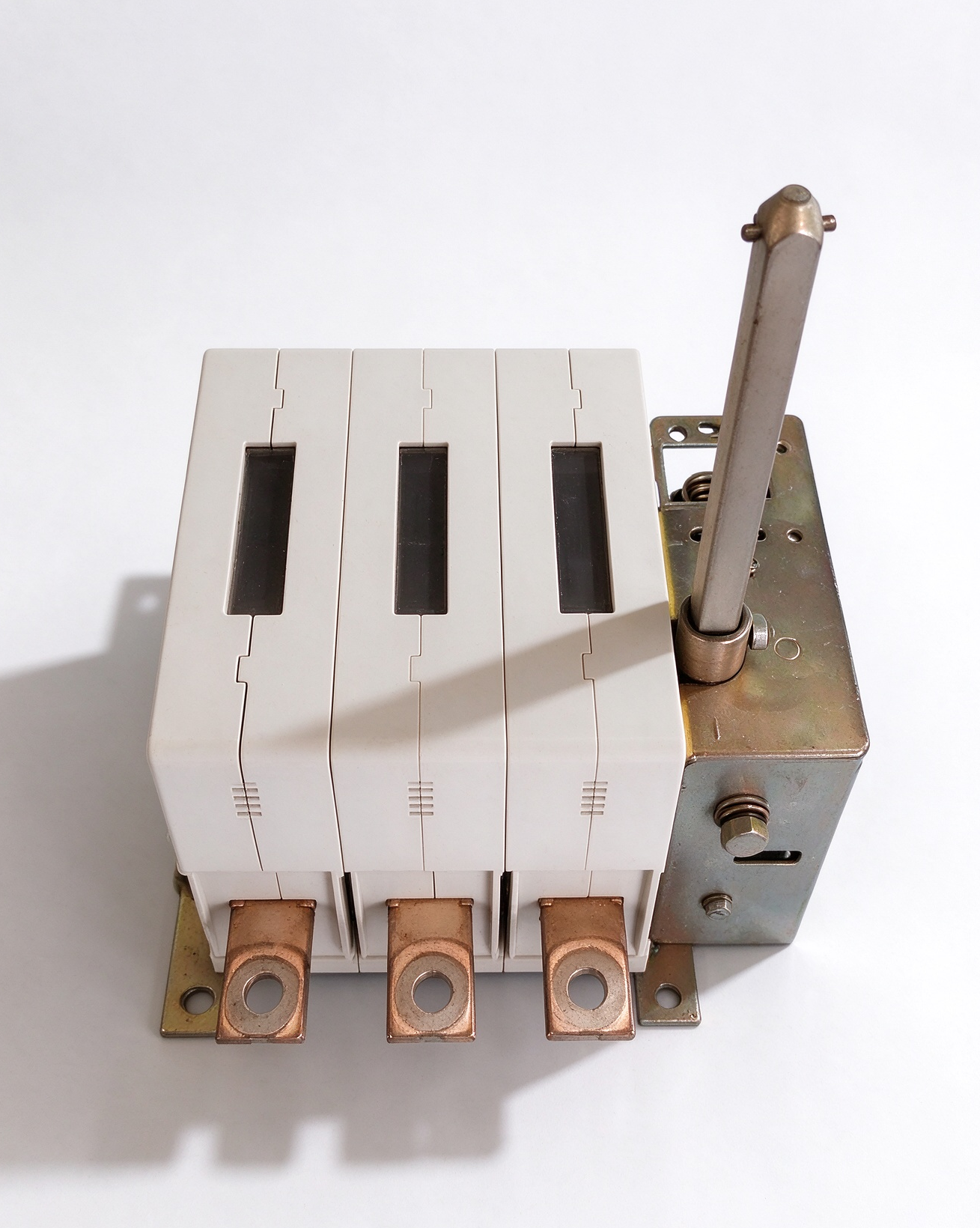
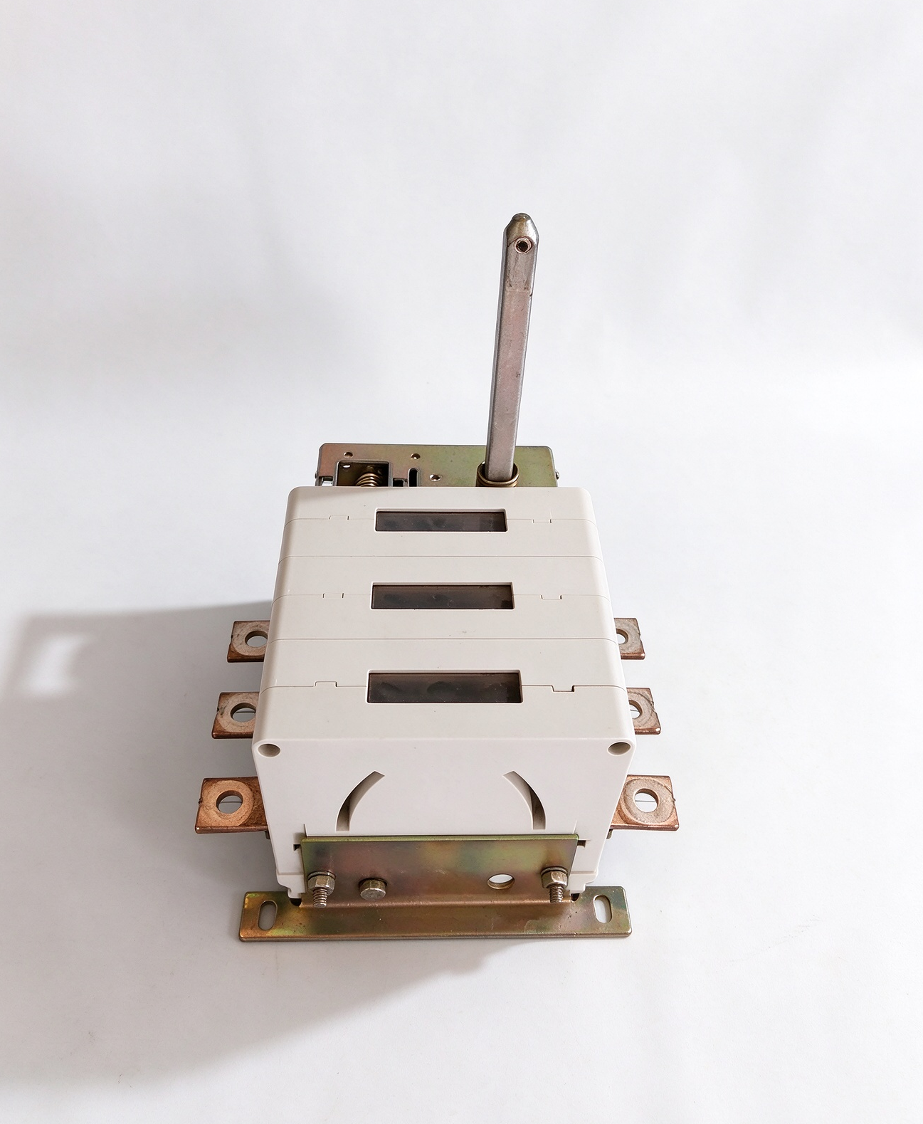
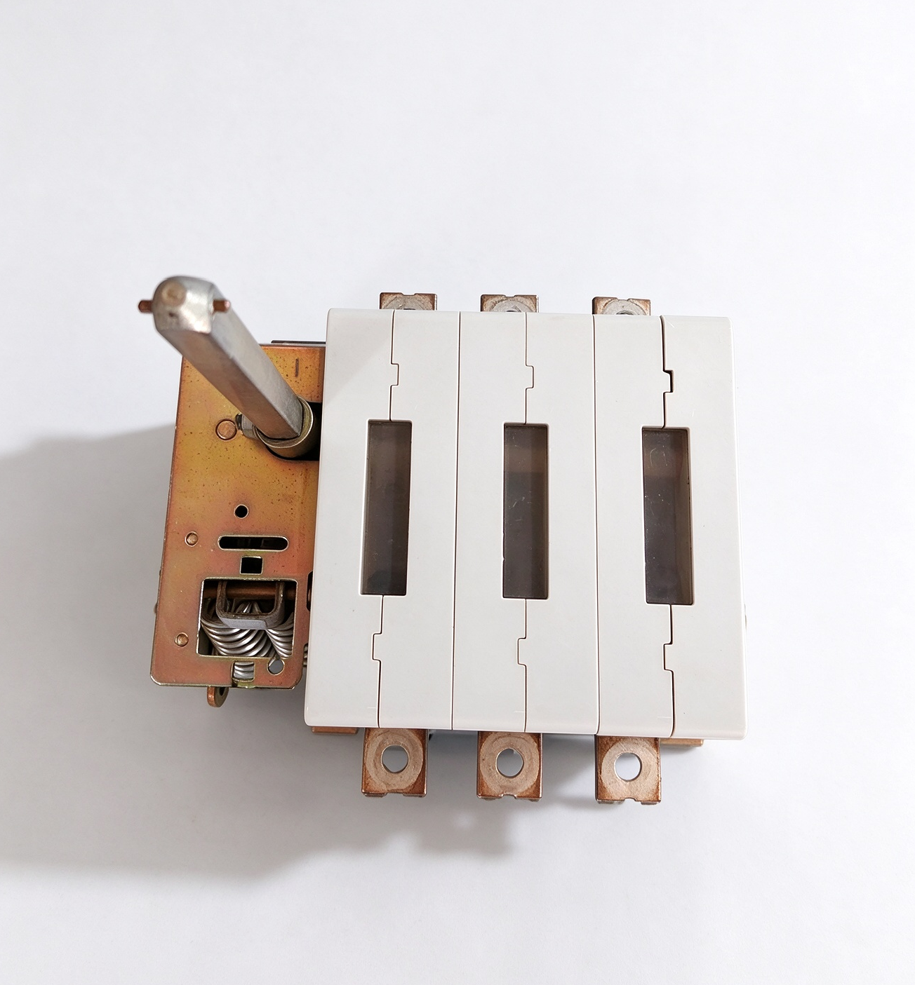
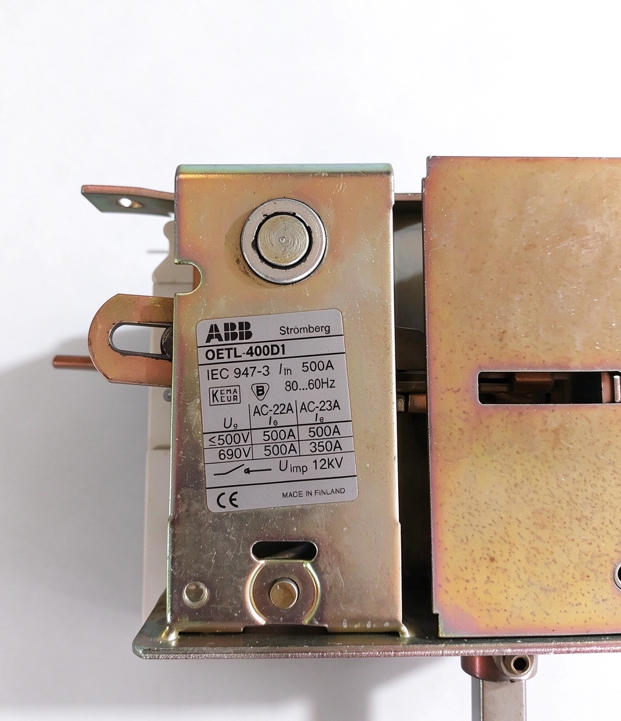
ABB 1SCA022058R0020 OETL 400D1 400A Three-Pole Load Break Switch
Product Overview
The ABB 1SCA022058R0020 is the ordering reference associated with the OETL 400D1 three-pole load break switch. This device belongs to ABB’s range of low-voltage switching products developed for electrical distribution and industrial power systems. Its primary function is to provide manual switching and electrical isolation within a correctly designed installation.
Load break switches are important components in distribution assemblies, machinery control panels, and industrial switchgear. They allow an operator to establish or interrupt an electrical circuit under the operating conditions specified for the selected switch. They may also provide a defined isolation point when equipment requires maintenance or when a section of an electrical installation must be separated from its supply.
The OETL 400D1 is identified within the 400-class switch family and is a three-pole configuration. The three-pole arrangement allows the associated switching mechanism to operate three circuit paths together. This configuration is commonly relevant to three-phase power distribution, where coordinated switching of the phase conductors is required.
When specifying the ABB 1SCA022058R0020, it is important to distinguish the product’s model designation from its applicable operational ratings. The current-carrying and switching capabilities depend on the relevant utilization category, operating voltage, installation conditions, and the manufacturer’s published specifications. These details should be checked before the switch is selected for a particular electrical system.
Operating Principle of the OETL 400D1
The OETL 400D1 uses a manually operated switching mechanism to open or close its main contacts. During operation, the mechanism moves the contacts between their defined switching positions. The design is intended to provide a controlled switching action in accordance with the requirements of the applicable ABB product documentation.
A load break switch differs from an ordinary isolating device in that it is designed for switching duties within specified operating limits. Its suitability for making or breaking a particular load depends on the rated operational current, voltage, and utilization category. It should not be assumed that every load break switch can interrupt every type of electrical load or fault current.
In a typical installation, the switch is incorporated into a power distribution circuit so that the designated circuit can be switched as required. Its operation may be part of a maintenance procedure, an equipment isolation sequence, or the normal operation of an electrical distribution assembly.
The switching mechanism, operating handle, shaft, and mounting arrangement must be compatible with the intended installation. The exact configuration should be confirmed using the applicable assembly drawings and installation instructions rather than inferred from the ordering reference alone.
Three-Pole Switching Configuration
The three-pole configuration is a central feature of the ABB OETL 400D1. In a three-phase electrical system, each pole corresponds to a separate switching path. Operating the common mechanism changes the state of the associated poles as designed, supporting coordinated switching of the circuit.
This arrangement is relevant to industrial distribution boards, motor supply circuits, and other three-phase electrical assemblies. A common operating mechanism can simplify manual operation by allowing the designated circuit paths to be switched together instead of requiring separate manual operations for individual poles.
System designers must determine which conductors are to be switched and how the device will be incorporated into the overall installation. Neutral switching requirements, protective earthing arrangements, and any special supply-system conditions must be assessed independently. A three-pole switch should not automatically be treated as a four-pole device or as a complete solution for every isolation requirement.
The selection process should also consider the required switching sequence and any mechanical or electrical interlocking associated with the surrounding equipment. Where multiple sources or alternative supplies are involved, the complete arrangement must prevent unsafe operating conditions and comply with the applicable electrical standards.
Electrical Ratings and Application Requirements
The ABB 1SCA022058R0020 is associated with the OETL 400D1 product designation and a 400A class description in product listings. However, the correct operational current rating for an installation must be established from the manufacturer’s technical data for the relevant voltage and utilization category.
For load break switches, utilization categories describe the type of electrical load and switching duty for which the equipment is intended. Resistive loads, motor loads, and other inductive circuits can impose different electrical demands on the switching contacts. As a result, a rating specified for one utilization category should not automatically be applied to another.
The system’s rated operational voltage is another essential selection factor. The selected switch must be appropriate for the nominal voltage and the actual operating conditions of the circuit. Designers should also evaluate the prospective short-circuit current and coordinate the switch with suitable upstream protective devices.
A load break switch does not necessarily provide overload protection or short-circuit protection by itself. Fuses, circuit breakers, or other protective equipment may be required according to the system design and the manufacturer’s instructions. The protection arrangement must be selected so that the switch is not exposed to fault conditions beyond its specified capabilities.
Before commissioning, confirm the complete model reference, applicable current and voltage ratings, utilization category, connection requirements, and coordination with protective equipment. These checks help ensure that the device is used within its intended electrical operating limits.
Mounting and Switchgear Integration
The OETL 400D1 is intended for integration into suitable low-voltage electrical assemblies. Its mounting arrangement must be compatible with the enclosure, busbar system, conductor layout, and operating mechanism selected for the application.
For front-operated installations, the handle and shaft arrangement is particularly important. The operating handle must be correctly aligned with the switch mechanism and mounted according to the manufacturer’s instructions. Where a door-mounted operating arrangement is used, the relationship between the enclosure door, shaft, and switch position should be checked throughout the required operating sequence.
ABB documentation for front-operated switch-disconnector configurations describes associated operating components and mounting hardware. The precise accessories supplied or required depend on the specific switch configuration and ordering reference. Engineers should therefore verify the relevant parts list before finalizing the enclosure design.
Electrical connections must be suitable for the specified conductors and the applicable terminal arrangement. Conductor size, lug selection, terminal hardware, tightening requirements, and phase clearance should follow the manufacturer’s instructions. Incorrect connections can lead to excessive resistance, overheating, or mechanical stress on the terminals.
Enclosure design should also account for accessibility, ventilation, cable bending space, insulation clearances, and protection against accidental contact with live parts. The complete assembly must satisfy the applicable installation and switchgear requirements.
Industrial Applications
The ABB 1SCA022058R0020 may be considered for low-voltage distribution and switching applications in industrial facilities. Potential installations include power distribution panels, industrial electrical cabinets, manufacturing equipment, and other systems that require manual switching of a three-phase circuit.
In distribution assemblies, a load break switch can provide a defined switching point for a section of the electrical system. This can help operators manage equipment operating states and carry out planned isolation procedures in accordance with established safety practices.
In industrial machinery, the switch may be incorporated into a power supply arrangement where the relevant circuit must be manually disconnected or reconnected. Its suitability depends on the connected load, the expected switching frequency, and the electrical ratings of the complete installation.
The product may also be relevant to electrical panel maintenance and equipment replacement projects. In these situations, the existing switch reference, mounting dimensions, pole configuration, shaft arrangement, and electrical requirements should be compared with the proposed replacement before any modification is made.
These examples describe general application areas rather than confirming suitability for every system. A qualified designer must evaluate the complete installation, including fault protection, isolation requirements, interlocking, and any additional safety measures.
Safety and Maintenance Considerations
Safe operation of a load break switch requires correct installation, suitable protective equipment, and adherence to established electrical work procedures. Personnel should identify all relevant energy sources and follow the applicable isolation and verification procedures before working on connected equipment.
The switch’s operating position should be clearly identifiable as required by the installation. Where the design includes door interlocking or other mechanical safeguards, these features should be installed and maintained according to the manufacturer’s instructions. Any interlocking arrangement must be assessed as part of the complete switchgear design.
Maintenance inspections should follow the manufacturer’s recommendations and the site’s maintenance schedule. Depending on the installation, relevant checks may include the condition of the operating mechanism, mounting hardware, electrical connections, insulation components, and visible signs of overheating or mechanical damage.
If abnormal switching behavior, unusual resistance, or visible damage is identified, the equipment should be assessed by qualified personnel before it is returned to service. Repairs and adjustments must follow the applicable technical instructions. The switch should not be modified in a way that compromises its rated performance or safety characteristics.
Product Selection and Replacement Guidelines
When selecting the ABB OETL 400D1, begin by verifying the complete ordering reference, 1SCA022058R0020, and the three-pole configuration. Next, establish the circuit’s operating voltage, normal load current, utilization category, and required switching duty. These details are essential because similar switch models may have different ratings or mechanical arrangements.
For replacement projects, compare the existing device’s mounting configuration, terminal positions, shaft dimensions, operating handle, and enclosure requirements. A switch with a similar current designation may not be a direct mechanical replacement if its dimensions or accessory arrangements differ.
The electrical protection scheme must also be reviewed. Confirm that upstream protective devices are suitable for the installation and that the switch’s published ratings are consistent with the expected operating and fault conditions. Where the switch is part of a larger assembly, changes should be evaluated against the assembly’s original design requirements.
Using the complete ordering reference and the applicable ABB technical documentation helps reduce uncertainty during selection, installation, and maintenance. It also provides a reliable basis for confirming that the switch matches the intended application.
Product Summary
The ABB 1SCA022058R0020 OETL 400D1 is a three-pole load break switch associated with low-voltage power distribution and manual switching applications. Its design supports coordinated switching of three circuit paths within a suitable electrical installation.
Correct application depends on verifying the operational current and voltage ratings, utilization category, short-circuit protection, terminal requirements, and mounting arrangement. The switch must be integrated into a properly designed electrical system and operated according to the manufacturer’s instructions.
For engineering selection, equipment replacement, and maintenance planning, the complete model reference should be used together with the applicable ABB product documentation. This approach helps establish the suitability of the OETL 400D1 for the intended electrical switching function.

评价
目前还没有评价