
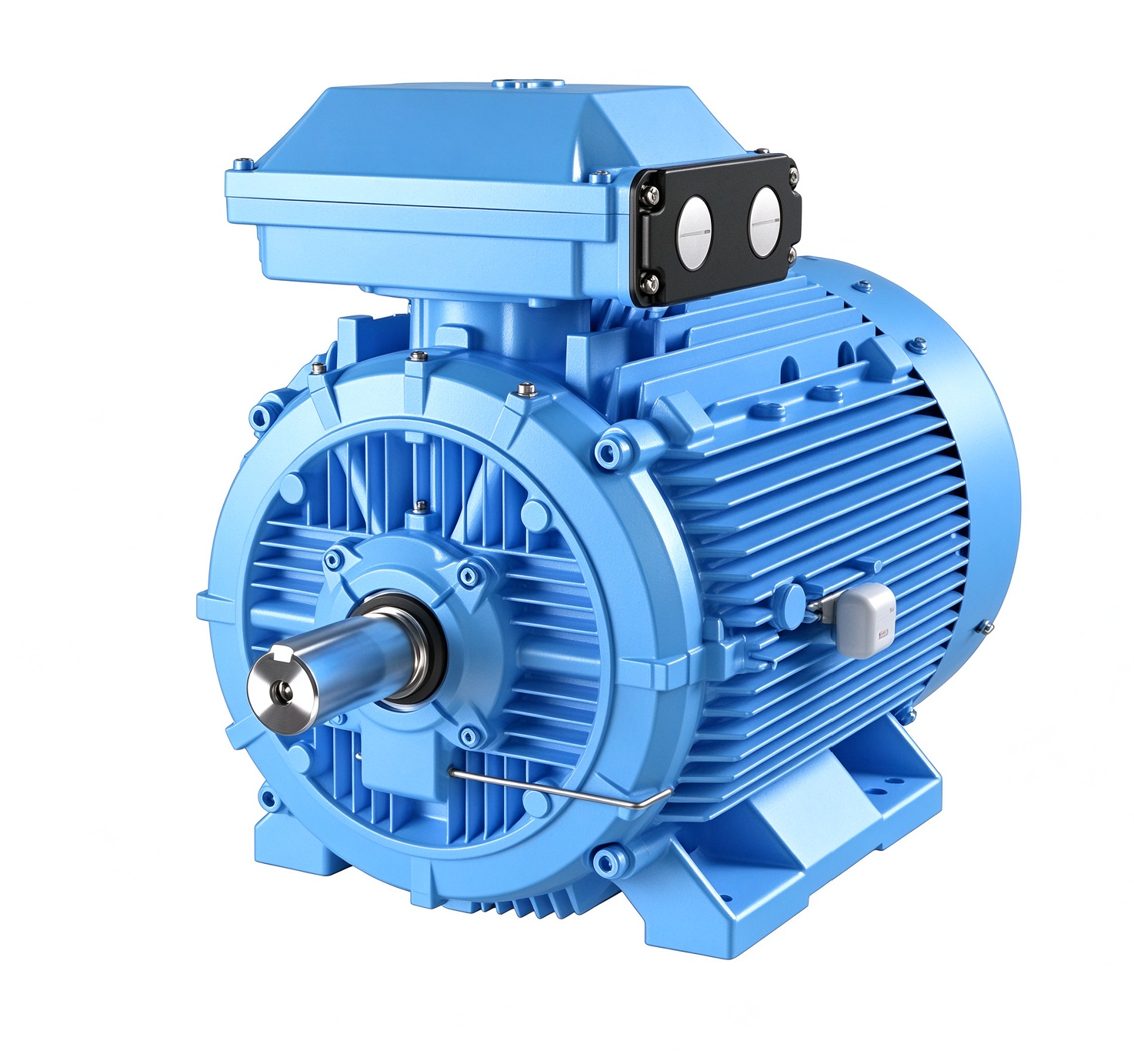
ABB M3BC 315MLA 2 B3 IC411 Industrial Electric Motor
The ABB M3BC 315MLA 2 B3 IC411 is an industrial electric motor identified by its model designation, frame configuration, mounting arrangement, and cooling classification. Correct identification of these characteristics is essential when selecting a motor for an industrial drive, planning a replacement, or checking compatibility with existing mechanical equipment. Before installation, the complete nameplate information and the applicable technical documentation should be reviewed to confirm that the motor meets the requirements of the intended application.
Product Overview
The ABB M3BC 315MLA 2 B3 IC411 belongs to an industrial motor configuration intended for integration into machinery and driven equipment. In industrial environments, electric motors convert electrical energy into mechanical rotation, supplying the torque required by pumps, fans, compressors, conveyors, and other rotating machinery. The selection of a suitable motor depends on more than its model number. Electrical supply conditions, rated output, speed, load characteristics, environmental conditions, mechanical dimensions, and installation requirements must all be considered together.
The designation provided for this motor contains several important identification elements. The M3BC series designation identifies the motor family, while 315MLA 2 identifies the stated frame and pole configuration. B3 refers to a foot-mounted construction, and IC411 identifies a cooling arrangement under the IEC motor cooling classification system. These designations help engineers and maintenance personnel organize equipment records, assess installation compatibility, and distinguish the motor from products that have different mechanical or cooling arrangements.
Although motors can share a similar frame designation, their electrical ratings and construction details may vary according to the particular product configuration. Therefore, the model designation should be used as the starting point for identification rather than as a substitute for the complete technical specification.
Motor Designation and Configuration
The designation M3BC 315MLA 2 B3 IC411 combines information about the motor family, frame configuration, mounting style, and cooling method. Understanding these elements is useful when reviewing equipment schedules or comparing a proposed motor with an installed unit.
The 315MLA frame designation indicates a particular dimensional configuration within the motor family. Frame information is important because it affects the relationship between the motor feet, shaft center height, shaft extension, and connected machinery. During a replacement project, the overall frame designation alone may not confirm a complete mechanical match. Shaft dimensions, mounting-hole spacing, shaft height, coupling geometry, and available installation clearance should also be checked against the original equipment requirements.
The numeral 2 in the model designation indicates a two-pole configuration. Motor speed is influenced by the number of poles and the electrical supply frequency. Actual operating speed is also affected by the induction motor’s slip and operating conditions. Consequently, the expected speed should be verified using the rated information on the motor nameplate rather than inferred from the model designation alone.
The full model reference should be retained in procurement records, maintenance documentation, and equipment registers. Recording the complete designation reduces the risk of confusing motors that have similar frame sizes but different mounting arrangements, electrical specifications, or cooling configurations.
B3 Mounting Arrangement
The B3 mounting designation identifies a foot-mounted motor arrangement. In this configuration, the motor is supported by mounting feet that are secured to a suitable foundation, machine bed, or supporting frame. This arrangement is commonly used in industrial installations where the motor is positioned horizontally and connected to driven equipment through a coupling, belt drive, gearbox, or another compatible transmission system.
Correct mounting is important for mechanical stability and reliable operation. The supporting surface should provide adequate rigidity and be suitable for the loads and vibration associated with the complete rotating assembly. The mounting feet must be secured according to the applicable installation instructions, and the motor should be aligned with the driven machine before the equipment is placed into service.
Misalignment between the motor shaft and the driven equipment can introduce additional loads on bearings, couplings, and connected components. Uneven foundations or improperly secured mounting feet may also contribute to vibration. Installation planning should therefore include an assessment of foundation condition, shaft alignment, coupling requirements, and the accessibility of maintenance points.
When replacing an existing motor, engineers should confirm the mounting dimensions and shaft arrangement rather than relying exclusively on the B3 designation. Any differences in dimensions or connected equipment requirements should be resolved before mechanical installation begins.
IC411 Cooling Method
IC411 is a cooling classification used for enclosed electrical machines. It generally describes a totally enclosed, fan-cooled arrangement in which an external fan mounted on the motor shaft moves cooling air over the outside surface of the motor frame. Heat generated within the motor is transferred through its internal structure to the frame and then dissipated into the surrounding air.
This cooling arrangement is widely associated with industrial motors because it provides a defined cooling method without requiring the internal motor space to be directly ventilated by the external cooling airflow. The enclosed construction and cooling arrangement must nevertheless be understood in the context of the complete motor design. An IC411 designation does not by itself establish an ingress protection rating or confirm suitability for every environmental condition.
For effective heat dissipation, the motor should be installed in a location where cooling air can circulate around the housing. Ventilation openings and the external fan cover should be kept clear of obstructions, excessive dust accumulation, and materials that could restrict airflow. High ambient temperatures, nearby heat sources, and restricted ventilation can affect the motor’s thermal operating conditions.
Maintenance personnel should inspect the cooling fan, fan cover, external surfaces, and surrounding clearance as part of the equipment maintenance program. Any abnormal noise, visible damage, or substantial buildup of material should be investigated according to the manufacturer’s instructions. The specified cooling arrangement should not be modified without confirming that the proposed change is technically appropriate.
Industrial Applications
Industrial electric motors are used in a broad range of applications that require controlled and continuous mechanical rotation. Depending on its verified electrical ratings, mechanical characteristics, and operating limits, a motor in this configuration may be considered for compatible pumping systems, industrial fans, air-handling equipment, conveyors, process machinery, and other motor-driven installations.
In pumping applications, the motor supplies the mechanical input needed to drive the pump shaft. Correct selection requires consideration of the pump duty point, required shaft power, operating speed, starting conditions, and the characteristics of the pumped medium. The motor must be matched to the actual load and the expected operating cycle.
For fan and ventilation equipment, the relationship between speed, airflow, pressure, and mechanical load should be considered when determining whether the motor is suitable. Conveyor and process machinery applications may place different demands on starting torque, acceleration, load variation, and operating duration. These factors should be evaluated before confirming a motor selection.
The model designation alone does not establish suitability for hazardous locations, outdoor exposure, washdown conditions, or other specialized environments. Where such conditions exist, the required enclosure protection, temperature limits, certifications, and any additional construction features must be verified from the relevant documentation.
Electrical Installation and Operating Considerations
Before connecting the ABB M3BC 315MLA 2 B3 IC411 to an electrical supply, qualified personnel should compare the available supply with the motor nameplate. Important information includes rated voltage, frequency, phase configuration, rated current, connection arrangement, power rating, and any applicable duty or operating limitations. These values must not be assumed solely from the model reference.
The motor starter and protective devices should be selected in accordance with the confirmed motor ratings and the requirements of the installation. Appropriate protection may include short-circuit protection, overload protection, and other measures required by the system design and applicable electrical regulations. The starting method must also be compatible with the supply capacity, the connected load, and the motor’s electrical characteristics.
Where a variable frequency drive is used, compatibility should be confirmed for the specific motor and operating range. Drive parameters, acceleration and deceleration settings, low-speed cooling conditions, and permitted operating limits should follow the relevant technical instructions. A drive should not be assumed suitable merely because the motor is an industrial induction motor.
Protective earthing, cable selection, terminal connections, and electrical isolation procedures must be completed according to applicable standards and site safety requirements. Installation and maintenance should be carried out by personnel with appropriate qualifications. Before opening terminal enclosures or working on the machine, the equipment must be isolated and secured against unintended energization.
Maintenance and Condition Monitoring
A planned maintenance program can help identify developing mechanical, electrical, and thermal issues before they lead to an unexpected interruption. The inspection frequency should reflect the operating environment, duty cycle, criticality of the driven equipment, and the manufacturer’s recommendations.
Routine checks may include observing abnormal vibration, listening for unusual bearing or fan noise, checking the mounting arrangement, reviewing motor temperature, and inspecting the external cooling surfaces. Changes in current, temperature, noise, or vibration may indicate a developing issue, but individual symptoms should not be used as the sole basis for a diagnosis.
Lubrication requirements, bearing maintenance intervals, and permitted service procedures depend on the specific motor construction and documentation. Maintenance personnel should verify the correct lubricant, lubrication quantity, and maintenance interval where applicable. Unspecified lubricants or maintenance practices should not be adopted without confirming compatibility with the installed motor.
Recording operating observations and maintenance actions helps establish a useful condition history. Such records can support troubleshooting, identify recurring installation problems, and improve planning for maintenance activities. Any repair or replacement work should preserve the relevant mechanical and electrical requirements of the motor assembly.
Model Verification and Replacement Selection
When evaluating the ABB M3BC 315MLA 2 B3 IC411 for a new installation or as a replacement for an existing motor, the first step is to verify the full model designation and the information shown on the nameplate. The electrical supply, rated output, rated speed, current, mounting dimensions, shaft details, cooling arrangement, and environmental requirements should be compared with the installation specifications.
It is also important to establish whether the application operates continuously or intermittently, whether the driven load varies significantly, and whether the motor is controlled directly from the supply or through a drive. These factors influence the suitability of the proposed configuration and may affect the selection of protection, starting equipment, and control parameters.
For equipment replacement, the existing motor’s physical dimensions and connection details should be documented before removal. Differences in terminal position, cable entry, shaft extension, mounting-hole layout, or accessories can affect installation even when two motors appear similar. A compatible replacement should meet both the electrical requirements and the mechanical demands of the complete drive system.
Conclusion
The ABB M3BC 315MLA 2 B3 IC411 is identified by a motor designation that specifies its product family, frame configuration, two-pole arrangement, B3 foot mounting, and IC411 cooling classification. These characteristics provide a useful starting point for engineering review, maintenance planning, and replacement selection.
Reliable application depends on confirming the complete technical specification rather than relying on the model designation alone. Electrical ratings, mounting dimensions, cooling conditions, load requirements, protective measures, and the installation environment should all be checked against the applicable documentation. By verifying these details before installation and maintaining appropriate operating records, engineers and maintenance teams can make better-informed decisions about integrating the motor into an industrial drive system.

评价
目前还没有评价