
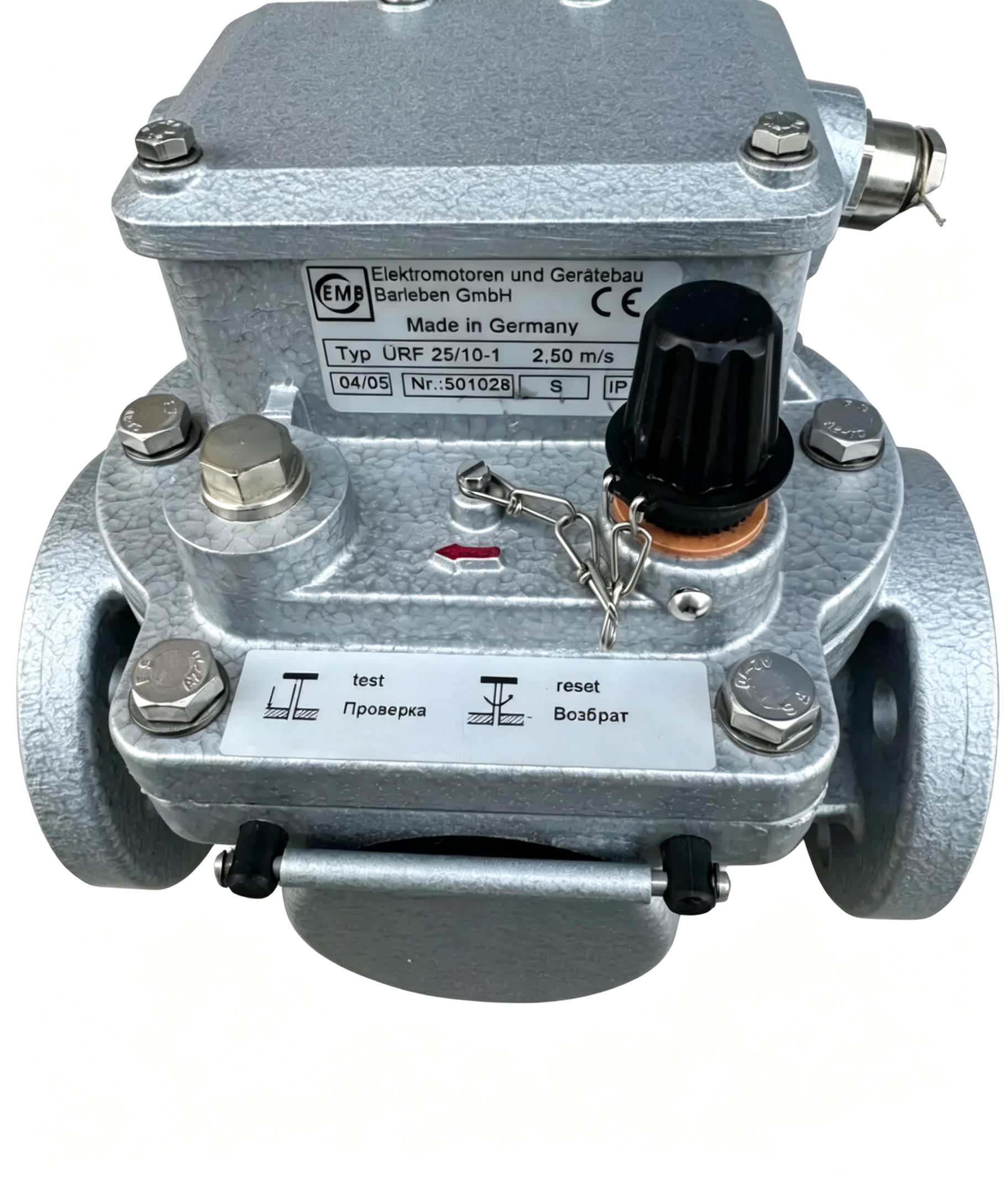
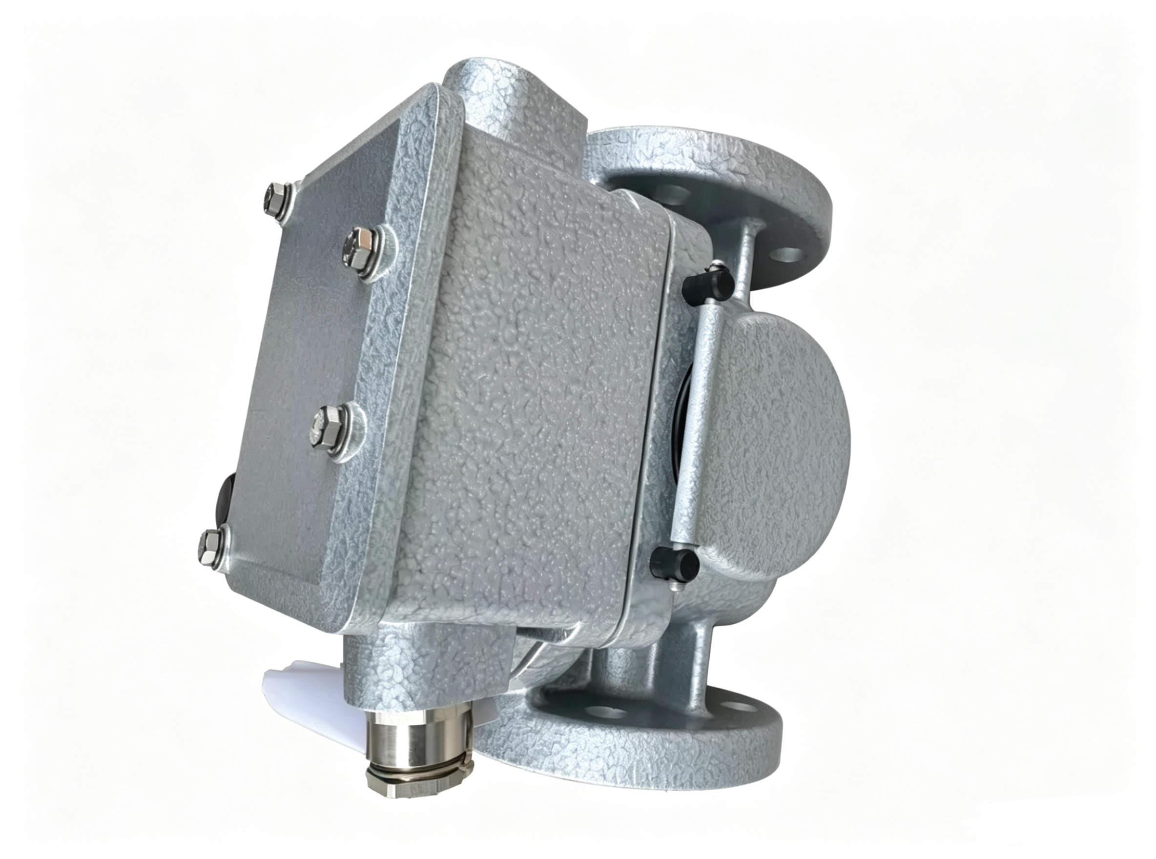
ABB URF 25/10 Oil Flow Relay
ABB URF 25/10 is an oil flow monitoring relay used in protection arrangements for oil-filled on-load tap changers. The device is designed to detect an abnormal oil flow condition between the tap changer compartment and the expansion vessel and generate a switching signal when the selected flow velocity threshold is exceeded. The URF 25/10 is commonly associated with transformer and autotransformer tap changer protection systems where rapid oil movement can indicate an internal fault or abnormal event within the tap changer compartment.
The URF 25/10 is a flow-operated protective device rather than a conventional pressure transmitter or general-purpose control relay. Its mechanical sensing element responds directly to the movement of transformer oil through the relay body. When the oil flow reaches the selected operating value, the sensing plate moves and actuates the magnetic contact mechanism, allowing the relay to initiate the associated protection circuit.
Product Identification
The product designation URF 25/10 identifies a specific oil flow relay design used for on-load tap changer protection. Available technical documentation identifies URF 25/10 as a jet or oil-flow relay for oil-filled tap changers. The device is installed in a pipeline with a nominal diameter of 25 mm and is positioned between the tap changer tank and the expansion vessel.
- Product designation: URF 25/10
- Product type: Oil flow relay
- Application: On-load tap changer protection
- Measured condition: Oil flow velocity
- Nominal pipeline diameter: 25 mm
- Sensing element: Pressure plate
- Switching mechanism: Magnetic contact arrangement
- Installation location: Oil pipeline between tap changer and expansion vessel
- Function: Protective trip signal
- Available flow settings: 0.9, 1.2, 1.5, 2.0 and 2.5 m/s depending on version
Purpose of the Oil Flow Relay
An on-load tap changer contains switching components and insulating oil within its own compartment. If an internal fault occurs, the resulting energy release can produce rapid movement of oil toward the expansion vessel. Monitoring this flow provides a direct method of detecting a potentially dangerous condition.
The URF 25/10 is designed to respond to this abnormal oil movement. Under normal operating conditions, the sensing plate remains in its defined position. When oil flow exceeds the selected threshold, the plate moves against the mechanical restoring force and causes the magnetic actuator to approach the contact tube.
The resulting contact operation can be connected to a transformer protection circuit, relay logic, alarm system, or circuit-breaker trip arrangement according to the overall transformer protection design.
Mechanical Operating Principle
The URF 25/10 consists of a housing and cover assembly containing the sensing mechanism. A shaped steel bracket mounted to the cover supports the pressure plate. Under normal conditions, the pressure plate is held in its initial position by a weight mechanism.
When the velocity of the oil flowing through the relay exceeds the selected setting, the pressure plate rotates. The associated weight moves upward, bringing a circular magnet closer to the magnetic contact tube. The contact then changes state and provides the electrical switching signal required by the protection system.
This operating principle allows the relay to detect the hydraulic effect of abnormal oil movement without requiring a separate electronic flow sensor.
Flow Velocity Settings
The URF 25/10 is available with two principal ranges of selectable oil-flow settings. The first version provides settings of 0.9, 1.2 and 1.5 m/s. The second version provides settings of 1.5, 2.0 and 2.5 m/s.
Selection of the operating point is achieved by repositioning the weight along its holder. The selected flow velocity is indicated through the corresponding opening in the weight holder. This mechanical adjustment allows the relay to be configured according to the protection requirements of the associated tap changer.
The specified operating threshold should be selected according to the transformer manufacturer’s protection design and the requirements of the particular on-load tap changer.
Transformer and OLTC Protection
The primary application of URF 25/10 is protection of oil-filled on-load tap changers. It is installed in the oil circulation path leading from the tap changer compartment toward the expansion vessel.
During normal tap changer operation, oil movement remains within the expected operating conditions. An internal fault may produce a significantly higher flow velocity. The relay responds to this condition and provides a trip signal that can be incorporated into the overall transformer protection scheme.
The oil flow relay therefore acts as a dedicated protective interface between the mechanical oil system of the tap changer and the electrical protection system of the transformer.
Installation Direction
Correct installation direction is essential for the URF 25/10. Direction arrows are provided on the relay housing and cover to indicate the required oil-flow direction toward the expansion vessel.
The relay should be installed in the pipeline between the tap changer tank and its expansion vessel, with the oil-flow direction corresponding to the marked direction on the device. The pipeline arrangement should also comply with the applicable tap changer installation requirements.
Technical guidance indicates that the pipeline from the tap changer toward the expansion vessel should have an upward inclination, with an installation slope of approximately 2–4 percent used in the referenced application guidance.
Contact and Switching Function
The URF 25/10 uses a magnetic contact arrangement operated by the movement of the sensing mechanism. When the pressure plate reaches the required position, the magnet actuates the contact tube.
The switching contact can be connected to the electrical protection circuit associated with the tap changer. Depending on the complete relay configuration, contact arrangements can differ. Therefore, the actual contact configuration should be verified from the relay nameplate and applicable technical documentation before connection.
The electrical interface should be coordinated with the protection relay, alarm circuit, or circuit-breaker trip circuit used by the transformer installation.
Reset Function
After an operating event, the URF 25/10 can be returned to its normal position through the reset mechanism provided on the relay. Technical operating guidance describes a reset button located under the upper cover area.
The reset operation should be performed carefully and according to the applicable maintenance procedure. After resetting, the position of the weight should be visually checked through the inspection arrangement to confirm that the sensing mechanism has returned to its intended normal position.
A reset should only be performed after the cause of the protective operation has been investigated and the associated equipment has been determined to be safe for return to service.
Environmental Characteristics
Technical documentation for URF 25/10 specifies an operating ambient temperature range of approximately -40 to +40 °C under the stated oil viscosity conditions. The maximum oil operating temperature is specified as up to 100 °C continuously, with operation up to 120 °C permitted for a limited period of one hour.
These environmental limits are important when installing the relay on transformers operating under different ambient and oil-temperature conditions. The surrounding installation should remain within the applicable technical limits.
Electrical Insulation
The URF 25/10 insulation system is specified to withstand a test voltage of 1000 V at 50 Hz for one minute. The open relay contacts are specified to withstand a test voltage of 500 V.
These values are relevant when considering insulation coordination, commissioning checks, and electrical maintenance procedures. Testing should be performed using procedures appropriate for the complete transformer protection system.
Mechanical Dimensions
The URF 25/10 has a compact mechanical structure suitable for installation in the oil pipeline associated with an on-load tap changer. Technical data specifies approximate overall dimensions of 206 mm in length, 200 mm in width and 170 mm in height, with a mass of approximately 3.9 kg.
The physical dimensions should be considered when planning the pipe arrangement, support structure, access area and inspection position around the tap changer installation.
Vibration and Mechanical Resistance
The relay is designed for operation in transformer installations subject to mechanical vibration. Technical documentation specifies vibration resistance with acceleration levels dependent on frequency and describes resistance to repeated vertical shock loading.
This mechanical capability is important because transformers and tap changers can experience vibration during switching operations and under normal operating conditions. Correct mechanical mounting and pipeline support remain essential for maintaining the intended operation of the relay.
Application in Transformer Protection Systems
The URF 25/10 is normally integrated into a broader protection system rather than used as an independent monitoring device. Its switching contact can be connected to protective relays or control circuits responsible for generating alarms or initiating transformer disconnection.
The flow relay is particularly relevant to tap changer compartments because its function is focused on oil movement caused by conditions inside the switching chamber. This complements other transformer protection functions that monitor the main transformer tank, electrical faults, oil level, temperature, or other operating parameters.
Technical Specification Table
| Parameter | URF 25/10 |
|---|---|
| Product type | Oil flow monitoring relay |
| Primary application | Oil-filled on-load tap changer protection |
| Nominal pipeline diameter | 25 mm |
| First flow-setting range | 0.9 / 1.2 / 1.5 m/s |
| Second flow-setting range | 1.5 / 2.0 / 2.5 m/s |
| Sensing element | Pressure plate |
| Switching principle | Magnetic contact operation |
| Approximate length | 206 mm |
| Approximate width | 200 mm |
| Approximate height | 170 mm |
| Approximate mass | 3.9 kg |
| Ambient operating temperature | -40 to +40 °C under specified conditions |
| Maximum oil temperature | 100 °C; up to 120 °C for one hour |
| Insulation test voltage | 1000 V AC, 50 Hz, 1 minute |
| Open-contact test voltage | 500 V |
Maintenance Considerations
Maintenance of a URF 25/10 should include inspection of the housing, cover, sensing plate, weight mechanism, magnetic contact system, electrical connections and pipeline installation. The flow-direction marking should remain clearly identifiable, and the sensing mechanism should move freely within its intended operating range.
The selected flow setting should also be checked against the tap changer protection requirements. Any unexplained relay operation should be investigated before resetting the device, because an abnormal oil-flow event may indicate an internal condition within the tap changer.
Product Identification
For engineering documentation, the complete designation should be recorded as URF 25/10 together with the individual relay type, contact configuration, flow setting and nameplate information where available. Some URF 25/10 ordering codes contain additional numbers that define the contact arrangement and selected damper or flow setting.
This is important because different URF 25/10 configurations can have different switching arrangements and operating thresholds. The complete product code should therefore be used when specifying a replacement or documenting an installed transformer protection component.
Conclusion
ABB URF 25/10 is an oil flow relay used in protection systems for oil-filled on-load tap changers. Its operating principle is based on the movement of a pressure plate caused by excessive oil flow toward the expansion vessel. The resulting mechanical movement actuates a magnetic contact and provides an electrical protection signal.
The URF 25/10 is available with selectable flow settings of 0.9, 1.2 and 1.5 m/s or 1.5, 2.0 and 2.5 m/s depending on the version. Its compact construction, defined installation direction, mechanical sensing mechanism and protective switching function make it suitable for integration into transformer tap changer protection systems.
For accurate equipment identification, engineering selection and maintenance, the complete URF 25/10 nameplate information should be considered together with the associated on-load tap changer and transformer protection scheme. Particular attention should be given to the selected flow velocity, contact configuration, installation direction, pipeline arrangement and applicable environmental conditions.

评价
目前还没有评价